The Role of As-Built Drawings in Long-Term O&M Success

On a 50 MWp utility-scale solar PV plant in Karnataka, a recurrent insulation resistance (Riso) earth fault tripped a 3.125 MW central inverter during heavy morning dew. Armed with the original Issued-For-Construction (IFC) electrical layout, the plant's Operation & Maintenance (O&M) team mobilized an excavator to locate the buried 1,500V DC string homerun trench. But the drawings showed a direct straight-line path across Block 4. In reality, during construction eighteen months prior, the EPC civil crew had encountered an impenetrable subsurface granite ridge and diverted the trench 25 meters eastward without updating the engineering dossier.
During the blind excavation, the backhoe bucket snagged and severed an energized 33kV armoured export feeder cable alongside the primary SCADA ring fiber conduit. What should have been a routine 2-hour string fuse or connector replacement metastasized into a catastrophic six-day plant shutdown, ₹34 Lakhs in emergency splicing kits, lost generation export, and a contentious legal battle between the asset owner and the EPC contractor over liquidated damages (LDs).
In the lifecycle of a 25-year solar photovoltaic asset, the transition from Engineering, Procurement, and Construction (EPC) to commercial O&M is the single most vulnerable milestone. Construction teams are incentivized to achieve Commercial Operation Date (COD) at maximum velocity. But when an asset owner accepts a rubber-stamped IFC drawing set instead of a rigorously audited, DGPS-validated As-Built Handover Dossier conforming to IEC 62446-1, they inherit an operational minefield.
1. The Inevitable IFC-to-Ground Reality Gap: Why Field Deviations Occur
No solar plant has ever been constructed exactly as originally drafted on a CAD workstation. Between theoretical pre-bid desk studies and the harsh ground reality of utility-scale acreage or industrial rooftops, field adjustments are mandatory and continuous:
- Geotechnical & Subsurface Obstructions: High water tables, unexpected underground utilities, unrecorded boulders, or hard basalt strata frequently compel civil contractors to alter cable trench paths, relocate inverter pad plinths, or adjust driven pile embedment depths per IS 2911.
- Supply Chain Component Substitutions: Global logistics and module procurement dynamics often lead to mid-stream bill of materials (BOM) changes. Swapping 575W modules for 585W TOPCon modules alters string voltages, current characteristics, and fuse sizing. Similarly, substituting String Monitoring Box (SMB) models or inverter MPPT tracker assignments shifts cable termination coordinates.
- Rooftop Structural Clashes: On C&I industrial rooftops, unrecorded HVAC ducts, fire hydrant lines, skylights, and roof purlin corrosion force mounting structure adjustments, changing module stringing sequences and cable tray drops.
- Statutory DISCOM & CEIG Directives: During pre-charging site inspections, the Chief Electrical Inspectorate to Government (CEIG) or State Transmission Utility (STU) inspectors frequently demand on-site alterations to CT/PT ratios, lightning arrester mast positions, or neutral grounding links before granting safety clearance.
When these field markups remain scrawled on weathered paper prints in site portacabins and never get incorporated into a finalized As-Built drawing set, the long-term O&M team is left operating in the dark.
2. How Inaccurate Drawings Cripple O&M: The High-Stakes Failure Vectors
Every hour a solar plant spends offline represents permanent, non-recoverable revenue loss. Accurate as-built documentation directly determines a plant's Mean Time to Detect (MTTD) and Mean Time to Repair (MTTR) across four primary failure vectors:
A. DC String Isolation & Drone Thermography Integration
Modern aerial infrared (IR) drone inspections identify cell hotspots, PID degradation, and open-circuit strings with pinpoint accuracy—generating GPS coordinates for anomalous modules. However, translating a thermal drone alert into physical rectification requires matching the GPS coordinate to the exact module string, string combiner box, and inverter MPPT input channel.
If string numbers were swapped during field pulling and never recorded on an as-built stringing layout, technicians must manually decouple hundreds of MC4 connectors under high DC voltage. This blind probing wastes entire work shifts and introduces severe arc-flash risks per NFPA 70E and IEC 62548.
B. Underground Cable Fault Location Without Blind Digging
Underground medium-voltage (11kV/33kV) and DC homeruns buried per IS 1255 are subject to cyclic thermal expansion, soil settlement, and rodent damage. When an insulation breakdown occurs, technicians utilize Time Domain Reflectometry (TDR) and surge wave acoustic "thumpers" to calculate fault distance along the cable length.
Without DGPS As-Built Trench Route: Survey Distance Error ±35m → Blind Excavation Risk
With As-Built GIS Mapping: Precision Trench Excavation Within ±0.5m of Actual Cable Fault
Without an as-built trench routing plan documenting surveyed DGPS waypoints, depth markers, and underground straight-joint coordinates, converting the calculated cable length into an excavation trench coordinate is virtually impossible. As demonstrated in our opening case study, blind digging frequently damages adjacent utility assets.
C. Switchyard Safety, Protection Relay Settings & LOTO Protocols
During high-voltage switchyard maintenance, Lockout/Tagout (LOTO) protocols depend entirely on the fidelity of the plant Single Line Diagram (SLD). If relay trip curves (ANSI 50/51/51N overcurrent and earth fault), CT/PT secondary ratios, or auxiliary DC control wiring were modified during commissioning without updating the SLD, maintenance technicians risk opening switchgear under unisolated conditions or defeating fail-safe mechanical interlocks (e.g., Castell keys).
D. Earthing Grid Integrity & Annual CEIG Audits (IS 3043:2018)
Solar farms contain hundreds of buried chemical and pipe earth electrodes connected by a subterranean copper or galvanized mild steel (GI) flat grid. Under IS 3043:2018 and CEA Safety Regulations, the overall earth resistance must remain below 1.0 Ω (and below 0.5 Ω for high-voltage switchyards). Without an as-built grounding layout marking the exact surveyed coordinates of every earth pit and disconnecting test link, O&M technicians cannot isolate individual pits for statutory annual fall-of-potential testing.
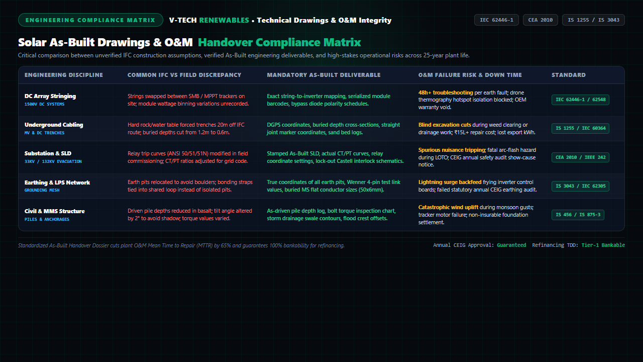
Figure 1: Comprehensive engineering compliance matrix comparing IFC shortcuts with As-Built benchmarks, field failure modes, and statutory Indian/IEC standards.
3. Regulatory, Warranty & Financial Ramifications
The value of as-built drawings extends far beyond routine maintenance troubleshooting. Incomplete handover documentation creates catastrophic legal, contractual, and financial liabilities:
Statutory CEIG Annual Re-Inspections
Under Central Electricity Authority (Measures Relating to Safety and Electric Supply) Regulations 2010 (Regulations 30 and 43), all electrical installations operating above 650V must undergo mandatory periodic statutory safety re-inspections by the Chief Electrical Inspectorate. During these audits, inspectors inspect switchgear nameplates, relay coordination schedules, and safety earthing against the official approved drawings on file. Any unapproved discrepancy triggers statutory notices, penalty levies, or immediate plant disconnection.
Tier-1 OEM Warranty Preservation
When a 3 MW central inverter power stack or an Inverter Duty Transformer (IDT) fails catastrophically, OEM forensic engineers investigate the root cause. If internal diagnostic logs reveal that field cabling, string input configurations, or protective relay trip coordination differed from the OEM-approved electrical schematics, the manufacturer will void the multi-crore equipment warranty, citing unauthorized field modifications.
Secondary Market M&A & Debt Refinancing Bankability
In the global renewable energy secondary market, operating assets are continuously acquired by institutional infrastructure funds (e.g., Brookfield, KKR, Actis, ReNew). During acquisition due diligence, the buyer's Owner's Engineer or Lender's Independent Engineer (LIE) conducts a rigorous Technical Due Diligence (TDD) audit. Missing or unverified as-built documentation is routinely classified as a "Tier-1 Red Flag," resulting in 2% to 5% equity valuation haircuts or substantial cash reserves held in escrow until complete reverse-engineering audits are completed.
4. The 7-Pillar As-Built Handover Dossier (IEC 62446-1 Framework)
To achieve true operational bankability and audit-proof handover, IEC 62446-1 mandates a comprehensive documentation package spanning seven specialized engineering disciplines:
Pillar 1: Stamped Electrical Single Line Diagrams (SLD)
Complete AC and DC evacuation architecture reflecting actual as-commissioned equipment: CT/PT accuracy classes (Class 0.2S for ABT metering), calibrated numerical relay curves (ANSI 50/51/51N/27/59/81), breaker trip ratings, DC disconnects, and captive DG interlock schematics.
Pillar 2: DC Array Layout & String-to-Inverter Schedules
Precise physical module layout showing string numbering, serialized module barcodes, DC disconnect box locations, homerun cable routes, and exact MPPT tracker assignments to enable seamless drone thermography cross-referencing.
Pillar 3: Underground Trenching & DGPS Cable Route Maps
Surveyed DGPS coordinates of all medium-voltage (33kV) and 1,500V DC cable trenches, cross-sectional depth profiles per IS 1255, positions of underground cable joint bays, road crossings, and warning tape depths to prevent excavation accidents.
Pillar 4: Earthing & Lightning Protection System (LPS) Layouts
Surveyed coordinates of all maintenance-free earth pits, transformer neutral grounding pits, lightning interception masts (rolling sphere method per IS/IEC 62305), buried 50×6mm GI flat ring routes, and baseline earth resistance test values.
Pillar 5: Civil & MMS Structural Foundation Handover
As-driven pile depth logs, static and lateral pile pull-out test reports per IS 2911, bolt torque inspection matrices, stormwater drainage swale profiles, and High Flood Level (HFL) finished floor elevations per IS 456.
Pillar 6: SCADA, Weather Station & Fiber Optic Topology
Optical Time-Domain Reflectometer (OTDR) baseline loss charts for all fiber loops, Modbus/DNP3/IEC 60870-5-104 communication point address lists, RTU/PLC wiring schematics, and Class-A pyranometer calibration certificates.
Pillar 7: Baseline Commissioning Test Records
Comprehensive cold and hot commissioning baseline documentation: open-circuit voltage ($V_{oc}$), short-circuit current ($I_{sc}$), string-level insulation resistance ($R_{iso}$), transformer oil dissolved gas analysis (DGA), and baseline IV-curve tracer curves for 25-year degradation tracking.
5. Pre-Handover As-Built Audit Checklist for EPCs & Asset Owners
Before issuing the Final Acceptance Certificate (FAC) or releasing the EPC's retention money, the asset owner's technical auditor must verify the following statutory checkpoints:
| Engineering Vector | Mandatory Handover Deliverable | Verification Method | Governing Standard |
|---|---|---|---|
| Electrical SLD | Stamped As-Built SLD with verified CT/PT ratios & relay trip curves | Secondary injection relay test cross-check; CEIG stamped file comparison | CEA 2010 / IEEE 242 |
| DC Stringing Layout | Serialized module string-to-MPPT map with barcode database | Drone thermal orthomosaic overlay; random field $V_{oc}$ string disconnect test | IEC 62446-1 / IEC 62548 |
| Underground Trenches | DGPS GIS route coordinates, joint bays & cross-section depth logs | Electromagnetic cable locator sweep; test pit depth confirmation (≥1.2m) | IS 1255 / IEC 60364 |
| Grounding Network | GPS-tagged earth pit layout with Wenner 4-pin baseline test logs | Fall-of-potential earth resistance test (≤1.0 Ω combined array; ≤0.5 Ω switchyard) | IS 3043:2018 / IEEE 80 |
| Civil MMS Foundations | As-driven pile depth log & certified pull-out test reports | 100% bolt torque wrench audit; stormwater drainage invert level verification | IS 2911 / IS 875-3 |
| Fiber & SCADA | OTDR trace baseline curves & Modbus point address mapping | Simulated transducer fault signal injection; SCADA alarm annunciator validation | IEC 60870-5-104 |
| Commissioning Baseline | Cold/hot commissioning logs: $V_{oc}$, $I_{sc}$, $R_{iso}$, transformer DGA test | Calibrated IV-curve tracer benchmarking; certified laboratory oil breakdown test | IEC 62446-1 / IS 10028 |
Frequently Asked Questions
1. What is the primary difference between Issued-For-Construction (IFC) drawings and As-Built drawings in a solar power plant?
Issued-For-Construction (IFC) drawings represent the theoretical engineering design approved prior to site execution, based on pre-construction geotechnical, topographic, and desk studies. In contrast, As-Built drawings record the exact, physical, on-ground reality of the completed installation after accommodating all field deviations. This includes DGPS coordinates of underground cable trenches rerouted around hard rock or buried utilities, verified module string numbering and inverter MPPT tracker mapping, actual relay trip settings and CT/PT ratios calibrated during commissioning, as-driven pile embedment depths per IS 2911, and certified earth electrode locations per IS 3043.
2. How do inaccurate or missing as-built drawings dramatically increase plant Mean Time to Repair (MTTR) during electrical faults?
When a 1,500V DC ground fault or 33kV cable insulation failure occurs, technicians rely on drawings to locate the fault. Without as-built DGPS trench routing and joint marker coordinates, field teams are forced into "blind digging" with backhoes, risking mechanical severance of adjacent energized feeder cables or SCADA fiber lines. Similarly, without accurate string mapping, isolating a single resistive hotspot or bypass diode failure flagged by aerial drone thermography requires technicians to manually test dozens of string combiner boxes under live DC load, extending troubleshooting downtime from 2 hours to 48 hours or more.
3. Why do Chief Electrical Inspectorate (CEIG) annual audits and OEM warranties mandate verified as-built documentation?
Under Central Electricity Authority (CEA Safety Regulations 2010, Regulations 30 and 43), operating solar installations must undergo mandatory periodic statutory re-inspections. CEIG officers cross-verify relay coordination curves (ANSI 50/51/51N), transformer neutral grounding links, and lock-out/tag-out (LOTO) key interlocks directly against stamped drawings. If on-site switchgear ratings or trip settings differ from documentation, inspectors issue show-cause notices or disconnection orders. Furthermore, tier-1 inverter and transformer manufacturers (e.g., Sungrow, SMA, TBEA) require stamped as-built Single Line Diagrams and commissioning logs to confirm operational parameters were not exceeded before honoring warranty claims on failed power electronics.
4. What core engineering deliverables are required in an IEC 62446-1 compliant As-Built Handover Dossier?
Per IEC 62446-1 (Photovoltaic systems – Requirements for testing, documentation and maintenance), a comprehensive as-built handover package comprises 7 critical pillars: (1) Stamped As-Built Single Line Diagram (SLD) with calibrated protection relay coordinates, (2) DGPS-mapped DC array layout and module string-to-MPPT assignment schedule, (3) Underground MV/DC cable trench cross-sections with surveyed depth and straight-joint markers per IS 1255, (4) Certified earthing and lightning protection grid layout with Wenner 4-pin test pit values per IS 3043:2018, (5) Civil structural foundation log with pile pull-out test certificates per IS 2911, (6) Fiber optic SCADA network topology with optical time-domain reflectometer (OTDR) baseline loss charts, and (7) Pre-commissioning baseline electrical test records (Voc, Isc, insulation resistance Riso, and IV curve traces).
Protect 25-Year Plant Yield with Bankable As-Built Engineering Audits
V-TECH RENEWABLES acts as Owner's Engineer and independent technical auditor, executing complete reverse-engineering surveys, DGPS underground asset mapping, and IEC 62446-1 as-built dossier handovers across Maharashtra, Gujarat, Rajasthan, Karnataka, and Pan-India.
Related Technical Engineering Guides
V-TECH RENEWABLES Engineering Consultancy
Founded in 2009 in Pune, Maharashtra, V-TECH RENEWABLES has engineered over 500+ MWp of commercial, industrial, and utility-scale solar PV installations. Our engineering team specializes in detailed electrical design, Owner's Engineer technical audits, IEC 62446-1 as-built verification, and fast-track statutory grid interconnection dossiers.