Inverter Station Layout Optimization: Saving Space and Installation Time
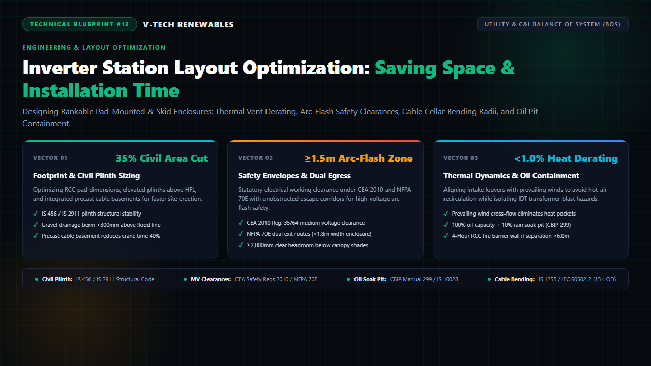
On a 30 MWp utility-scale solar plant in Solapur, Maharashtra, the project commissioning was abruptly halted by the Chief Electrical Inspectorate to Government (CEIG). The contractor had installed four 3.125 MW pad-mounted Inverter Duty Transformer (IDT) stations on cast-in-place concrete plinths that were squeezed tightly between module rows. The inspection team red-flagged three critical structural and electrical violations: the 33kV armoured XLPE evacuation cables were bent at acute angles under the gland plates violating manufacturer bending radii, the transformer oil soak pits lacked certified flame-quenching ballast, and cooling air intakes faced directly into the hot exhaust plumes of adjacent radiators.
During pre-commissioning full-load testing at 42°C ambient temperatures, the central inverters began severe thermal throttling—curtailing active power by 6.5% due to hot-air recirculation. Rectifying the plinth dimensions, excavating compliant cable basements, and retrofitting 4-hour fire barrier walls cost the EPC over ₹28 Lakhs in field modifications and three lost weeks of peak summer power generation.
In both utility-scale solar parks and large commercial & industrial (C&I) ground-mount plants, the Inverter Power Conditioning Station (PCS) is the beating heart of power evacuation. Yet, it frequently receives the least engineering layout scrutiny during pre-bid drafting. Achieving a compact, cost-effective, and audit-proof inverter station requires harmonizing civil foundation sizing, thermodynamic airflow modeling, high-voltage arc-flash safety envelopes, and strict cable mechanical protection.
1. The Balance of System Footprint Dilemma & Civil Plinth Sizing
Modern central inverter and clustered string inverter skid stations bundle massive electrical infrastructure into a compact rectangular footprint: 1,500V DC input switchgear, central inverter IGBT power modules, an Inverter Duty Transformer (stepping 690V/800V up to 11kV, 22kV, or 33kV), and a vacuum Ring Main Unit (RMU) circuit breaker.
Optimizing Civil Concrete Volume (IS 456 / IS 2911)
Civil works for inverter pads typically account for 8% to 12% of total civil Balance of System (BOS) expenditure. Oversized monolithic concrete slabs waste expensive Ready-Mix Concrete (RMC) and prolong curing timelines. Conversely, undersized pads lead to structural cracking under dynamic transformer vibration:
- Static & Dynamic Load Distribution: A typical 3.125 MVA to 6.25 MVA oil-filled transformer weighs between 10 and 18 metric tons. Plinths must be designed per IS 456:2000 using M25/M30 grade reinforced concrete with minimum reinforcement ratios designed to resist differential settlement across expansive black cotton soils common in Maharashtra, Madhya Pradesh, and Gujarat.
- Driven Pile Foundations: On low-bearing-capacity soils (safe bearing capacity <100 kN/m²), deploying short cast-in-situ bored piles (per IS 2911 Part 1/Sec 2) anchored beneath plinth beam corners eliminates massive shallow raft excavation, cutting concrete volume by 35%.
- High Flood Level (HFL) Elevation: Under CEA Grid Connectivity mandates and flood risk audit protocols, the top of the finished equipment plinth must sit at least 300 mm to 500 mm above the 50-year or 100-year High Flood Level (HFL). Surrounding the pad with a 1.2-meter wide crushed stone gravel apron (40mm metal) prevents soil erosion, facilitates storm drainage, and suppresses weed growth that could create fire hazards.
2. Thermal Aerodynamics & Ventilation: Preventing Summer Derating
Solar inverters are thermodynamic heat generators. Modern utility inverters operate at 98.5% to 98.8% conversion efficiency—meaning that 1.2% to 1.5% of full rated power is dissipated internally as sensible heat. In a 3.125 MW central inverter, this represents roughly 45 kW to 50 kW of continuous thermal energy dumped into the surrounding air during peak noon irradiance.
Required Airflow Q = P_loss / (ρ × c_p × ΔT) ≈ 8,500 - 12,000 m³/h
Critical Ambient Limit: T_ambient ≤ 50°C before IGBT Current Derating Initiates
Eliminating Hot-Air Recirculation Pockets
When central inverter skids are drafted without micro-climate analysis, internal cooling fans frequently discharge superheated exhaust air directly against boundary fences, solar table back-sheets, or adjacent transformer cooling fins. The exhaust air eddies back into the intake louvers, driving local ambient temperatures above 55°C. Under manufacturer operational curves (Sungrow, SMA, FIMER, Sineng), inverters throttle their Maximum Power Point Tracking (MPPT) capacity by 1.5% to 2.0% per degree Celsius above 50°C.
Layout optimization guidelines to safeguard PR (Performance Ratio):
- Wind Vector Alignment: Analyze site historical wind rose data. Intake louvers must be oriented perpendicular to or facing into the prevailing summer wind direction (typically South-West in peninsular India), while hot-air exhaust louvers face downwind.
- Physical Boundary Offsets: Maintain a strict minimum clearance of ≥2,500 mm (2.5 meters) on the exhaust side to prevent back-pressure resistance on internal centrifugal blowers.
- Ventilated Canopy Sunshades: Direct solar radiation adds an extra 8°C–12°C of skin temperature heating to outdoor enclosures. Installing a lightweight galvanized steel canopy with a 150mm top ventilation ridge gap shades the inverter enclosure while allowing natural convective chimney draft cooling.
3. Electrical Safety Clearances & Arc-Flash Egress (CEA 2010 / NFPA 70E)
Technician safety during energized maintenance and fault troubleshooting is non-negotiable. Squeezing inverter stations into narrow corridors creates fatal arc-flash traps where maintenance personnel cannot escape during an internal busbar flashover.
Statutory Clearances Under CEA Safety Regulations 2010
Under Central Electricity Authority (Measures Relating to Safety and Electric Supply) Regulations 2010 (Regulation 35 for Medium/High Voltage and Regulation 64 for Substations):
- Front Working Depth: For voltages between 650V and 33kV, an unobstructed clear working space of ≥1,500 mm to 2,000 mm must be maintained directly in front of open switchgear doors.
- Lateral Clearance: A minimum clear width of 1,000 mm must exist alongside all pad edges to allow two technicians to pass unhindered.
- Vertical Clearance: Canopy roofs and overhead bus duct supports must maintain a minimum clear headroom of ≥2,000 mm (ideally 2,400 mm) from the walking platform.
Dual Egress Protocols for High-Current Enclosures (NFPA 70E)
Under NFPA 70 (NEC Section 110.26(C)(2)), where equipment rated 1,200 Amperes or more contains overcurrent devices and exceeds 1.8 meters (6 feet) in width, there must be an unobstructed exit path at each end of the working space. If an arc flash occurs at one end of the inverter corridor, the technician must not be trapped against a dead end. Doors must open outwards in the direction of egress and be fitted with panic push-bars.
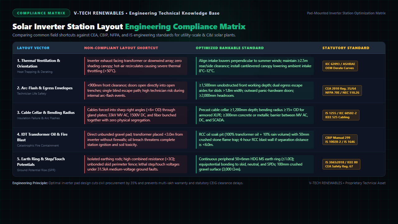
Figure 1: Comprehensive engineering compliance matrix detailing 5 core inverter station vectors, field failure modes, and statutory Indian/IEC benchmarks.
4. Cable Cellar Engineering & Strict Bending Radius Adherence
The mechanical transition of thick copper and aluminium power cables from underground trenches into inverter termination terminals is the single most common origin point of insulation failure and fire in solar farms.
The Danger of Cable Crushing (IS 1255 / IEC 60502-2)
A 33kV 3-core 300 mm² / 400 mm² Aluminium XLPE armoured cable has an outer diameter (OD) of approximately 85 mm to 95 mm. Under IS 1255 (Code of Practice for Installation and Maintenance of Power Cables up to 33kV) and IEC 60502-2, the minimum bending radius during installation is strictly:
When civil contractors construct shallow cable trenches (e.g., 600 mm depth), cable pullers are forced to use crowbars and mechanical winches to bend heavy cables at sharp 90-degree angles to enter bottom gland plates. This acute stress crushes the semi-conducting XLPE screen, creating micro-voids and mechanical kinks. Over 12 to 24 months of cyclic thermal expansion, electrical field concentration induces dielectric water-treeing, partial discharge, and catastrophic phase-to-earth flashovers inside the inverter marshaling box.
The Precast Concrete Cable Cellar Advantage
Rather than wrestling with narrow cast-in-place trenches, industry-leading solar engineering packages specify a precast concrete cable basement/cellar integrated directly beneath the inverter skid:
- Clear Working Depth: A sunken cellar with 1,200 mm to 1,500 mm depth provides ample sweeping room for cables to sweep upwards naturally conforming to the 15× OD bending radius.
- Physical EMI Segregation: The basement allows distinct multi-tier cable ladders: bottom tier for 33kV MV evacuation cables, middle tier for 1,500V DC string homeruns, and top tier separated by a continuous grounded metal barrier for RS-485 / SCADA fiber optic cables (conforming to IEEE 525).
- Rapid Crane Erection: Precast cellars are craned onto prepared compacted sub-grades in 2 hours, eliminating weeks of on-site formwork shuttering and curing delays.
5. Transformer Oil Containment Pits & Blast Walls (CBIP 299 / IS 10028)
Inverter Duty Transformers (IDT) contain between 2,500 and 5,000 liters of mineral insulating oil. If an internal winding flashover or tank rupture occurs, burning dielectric oil can spread rapidly across the plant, engulfing inverters, destroying SCADA RTUs, and contaminating local soil and groundwater.
Oil Soak Pit Design per CBIP Manual 299
Under CBIP Manual 299 and IS 10028 (Part 2), every oil-filled transformer installed in a solar farm must be equipped with an RCC oil containment pit:
- Volumetric Capacity: The pit must accommodate 100% of the transformer's total oil volume plus a 10% allowance for trapped rainwater.
- Flame-Quenching Ballast Layer: The pit must be capped with an open steel grating holding a minimum 150 mm thick layer of clean, uncrushed 40 mm–50 mm granite ballast stone. In the event of a catastrophic oil spill, burning oil filters through the stone matrix, which dissipates heat below the liquid's flash point, instantly extinguishing the fire.
- Gravity Drainage: An oil-water gravity separator pipe connects the soak pit to a remote centralized containment sump, preventing oil overflow during monsoon downpours.
Fire Barrier Blast Walls (IS 1646 / CEA Regulations)
Compact skid designs place the IDT transformer and central inverter within 2 to 3 meters of each other. Under IS 1646 (Code of Practice for Fire Safety of Buildings: Electrical Installations) and CEA regulations:
If the spatial separation distance between an oil-filled transformer and an adjacent inverter enclosure or building is less than 6.0 meters, a reinforced concrete Fire Barrier Wall (Blast Wall) with a certified 4-hour fire rating must be constructed. The blast wall must extend at least 1.0 meter higher than the top of the transformer conservator tank and 0.6 meters beyond both sides of the radiator fins.
6. Pre-Submission Inverter Station Checklist for Instant CEIG Approval
To eliminate regulatory objections and accelerate statutory synchronization, EPC design drawings must verify every parameter in this standardized compliance schedule:
| Station Vector | Minimum Engineering Dimension | Mandatory Drawing Callout | Statutory Standard |
|---|---|---|---|
| Civil Plinth & Elevation | ≥300 mm – 500 mm above 100-yr HFL | Finished floor level (FFL), gravel drainage apron, dynamic settlement checks. | IS 456 / IS 2911 |
| Arc-Flash Working Envelope | ≥1,500 mm front clear depth | Unobstructed door swing clearance, outward-opening dual egress with panic hardware. | CEA 2010 Reg. 35 / NFPA 70E |
| Thermal Intake & Exhaust | ≥2,500 mm clear on exhaust face | Wind vector arrow, vented canopy elevation, heat plume clearance boundaries. | IEC 62093 / ASHRAE |
| Cable Cellar & Bending Radius | ≥1,200 mm depth; Radius ≥15× OD | Cable cellar cross-section, ladder tiers, 300mm metallic MV/DC/SCADA barrier. | IS 1255 / IEC 60502-2 |
| Transformer Oil Soak Pit | 100% oil vol + 10% rain capacity | Pit dimensions, 150mm flame-quenching granite ballast, drainage sump link. | CBIP Manual 299 / IS 10028 |
| Fire Barrier Blast Wall | Mandatory if separation <6.0m | 4-Hour RCC wall detail (+1.0m above conservator, +0.6m beyond radiators). | IS 1646 / CEA Safety Regs |
| Station Peripheral Earthing | Combined impedance ≤1.0 Ω | 50×6mm HDG MS earth ring, IDT neutral pit, 100mm gravel layer (3000 Ω·m). | IS 3043:2018 / IEEE 80 |
Frequently Asked Questions
1. Why do utility-scale central inverter stations experience severe thermal derating, and how does layout engineering solve it?
Central inverters dissipate 1.5% to 2.5% of their rated capacity as sensible heat (approx. 45 kW to 75 kW per 3.125 MW PCS unit). When stations are installed with cooling air intakes facing the downwind side of adjacent transformer radiators or solar module tables, a micro-thermal recirculation trap occurs. Boundary layer temperatures quickly exceed 50°C during peak irradiance hours, forcing inverter IGBT power bridges into thermal curtailment and clipping generation by 4% to 8%. Engineering layouts resolve this by orienting intake louvers perpendicular to prevailing summer wind vectors, enforcing minimum 2.5m rear/lateral boundary clearances, and erecting cantilevered sunshades with top ventilation slots to lower intake air temperatures by 8°C to 12°C.
2. What are the statutory working clearances and arc-flash egress requirements under CEA 2010 and NFPA 70E for pad-mounted inverters?
Under Central Electricity Authority (CEA Measures Relating to Safety and Electric Supply) Regulations 2010 (Regulations 35 and 64) and NFPA 70E / NEC 110.26, electrical apparatus operating up to 1,000V AC / 1,500V DC requires a minimum clear front working depth of 1,200 mm to 1,500 mm with equipment doors fully unlatched at 90 degrees. For 11kV/33kV Ring Main Units (RMU) and medium-voltage switchgear, front working clearance must be at least 2,000 mm. Crucially, if an inverter enclosure or containerized power skid exceeds 1.8 meters (6 feet) in length with equipment rated above 1,200A, dual unobstructed egress paths equipped with outward-opening doors and panic hardware must be provided at opposite ends to guarantee escape during arc-flash incidents.
3. Why is a precast concrete cable cellar or basement superior to direct trenching for 33kV and 1500V cabling?
Direct trenching beneath inverter skids forces heavy multi-core armoured 33kV XLPE cables into sharp right-angle bends below the statutory minimum bending radius (mandated as ≥15× overall diameter per IS 1255 and IEC 60502-2). Severe mechanical bending crushes dielectric insulation, creates localized high electrical field stress, and triggers partial discharge flashovers. Integrating a precast concrete cable cellar with a minimum working depth of 1,200 mm provides generous curving radii, eliminates on-site trench excavation delays, slashes crane positioning time by 40%, and allows rigid physical segregation (≥300 mm concrete barriers) between medium-voltage AC, 1,500V DC string homeruns, and sensitive SCADA communication fiber.
4. What are the mandatory oil containment and fire separation rules for Inverter Duty Transformers (IDT) per CBIP Manual 299?
Under CBIP Manual 299 and IS 10028 (Part 2), oil-filled Inverter Duty Transformers containing over 2,000 liters of dielectric fluid must be installed over an RCC oil soak pit sized for 100% of the transformer's total oil volume plus a 10% allowance for trapped rainwater. The pit must be capped with an iron grating supporting a 150 mm thick bed of clean, uncrushed 40–50 mm granite ballast stone to act as a fire-quenching flame trap. Furthermore, if the spatial distance between the transformer tank and adjacent inverter enclosures or neighboring transformers is less than 6.0 meters, a 4-hour fire-rated RCC baffle blast wall (per IS 1646 and CEA regulations) must be erected to prevent thermal radiation from spreading a catastrophic tank rupture fire across the power station.
Eliminate Grid Inspection Delays with Optimized Substation & Inverter Layouts
V-TECH RENEWABLES delivers bankable, audit-ready inverter station and substation engineering packages conforming to CEA 2010, CBIP 299, IS 456, and NFPA 70E across Maharashtra, Gujarat, Rajasthan, Karnataka, and Pan-India.
Related Technical Engineering Guides
V-TECH RENEWABLES Engineering Consultancy
Founded in 2009 in Pune, Maharashtra, V-TECH RENEWABLES has engineered over 500+ MWp of commercial, industrial, and utility-scale solar PV installations. Our engineering team specializes in detailed electrical design, STAAD Pro structural modeling, NBC 2016 fire safety layouts, and fast-track statutory grid interconnection dossiers.