Earthing and Lightning Protection Layouts for Solar Farms
During the pre-commissioning synchronization of a 40 MWp utility-scale solar farm in Surendranagar, Gujarat, a severe thunderstorm struck 800 meters from the pooling substation. Although the direct flash terminated harmlessly into a perimeter transmission tower, the resulting earth potential gradient surged through the array field. Over 18 central inverter digital communication boards were destroyed, 42 string combiner box (SCB) surge arresters ruptured, and statutory CEIG safety inspectors immediately revoked provisional charging approval.
The post-mortem investigation uncovered a fatal engineering shortcut: the ground network had been designed using a single assumed soil resistivity figure without multi-depth stratification surveys, and the contractor had installed an uncertified "Early Streamer Emission" (ESE) mast that failed to provide rolling-sphere protective coverage over the peripheral module blocks.
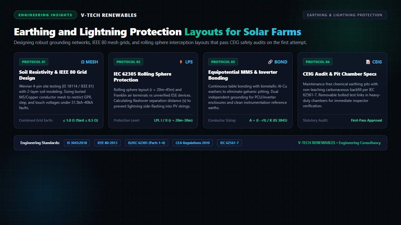
In utility-scale solar engineering, earthing and lightning protection systems (LPS) are not passive civil add-ons—they form the foundational electrical backbone that guarantees personnel safety, equipment survivability against 100 kA lightning discharges, and frictionless statutory grid commissioning. Designing a robust grounding network requires rigorous mathematical modeling across four critical vectors: soil resistivity stratification, IEEE 80 step and touch potential containment, IS/IEC 62305 rolling sphere interception geometry, and equipotential module table bonding.
1. Soil Resistivity Stratification & IEEE 80 Ground Grid Sizing
A dependable earthing layout begins in the field, not inside a CAD drawing. Soil across a 100-acre to 400-acre solar plant site is rarely uniform. Topsoils subject to seasonal moisture variations frequently conceal high-resistivity sandstone, granite, or caliche layers beneath.
Wenner 4-Pin Testing (IS 18114 / IEEE 81)
Engineers must execute four-terminal ground resistivity surveys per IS 18114 and IEEE 81 along orthogonal axes across every inverter block. By varying probe spacing ($a = 1\text{m}, 2\text{m}, 5\text{m}, 10\text{m}, 15\text{m}, 25\text{m}$), field teams calculate apparent soil resistivity ($\rho_a$):
Feeding these multi-depth datasets into computer modeling tools derives an accurate two-layer soil model: topsoil resistivity ($\rho_1$), bottom layer resistivity ($\rho_2$), and boundary depth ($h$). Relying on a generic assumed value (e.g., $50\,\Omega\cdot\text{m}$) in rocky terrain where true bedrock resistivity exceeds $800\,\Omega\cdot\text{m}$ results in severe under-sizing of the buried earth mat.
Conductor Cross-Section Sizing (IS 3043 / IEEE 80)
The main earthing conductor buried in perimeter trenches must withstand maximum symmetric line-to-ground fault current without thermal fusing. Under IS 3043:2018, minimum cross-sectional area ($A$) is governed by:
- Isc: System short-circuit fault current (typically 31.5 kA or 40 kA for 33 kV pooling substations).
- t: Fault clearing duration (mandated at 1.0 second for distribution networks, and 3.0 seconds where delayed breaker tripping applies).
- K: Material thermal constant (80 for hot-dip galvanized mild steel, 159 for bare annealed copper).
For a 31.5 kA / 1.0s fault in Indian soil conditions, a mild steel (MS) flat conductor requires a theoretical cross-section of $393.75\text{ mm}^2$. Adding the statutory corrosion allowance of 1.5mm to 2.0mm over a 25-year design lifespan per IS 3043 mandates specifying a minimum of 50 × 6 mm or 50 × 8 mm Hot-Dip Galvanized (HDG) MS flat for all main buried grid loops.
Touch and Step Voltage Thresholds
During an earth fault, high current dissipating into soil generates a localized Ground Potential Rise (GPR). Per IEEE 80-2013, the earthing grid design must ensure that calculated touch voltage ($E_{touch}$) and step voltage ($E_{step}$) remain below lethal physiological limits for an operator with a body weight of 50 kg or 70 kg:
In inverter rooms and transformer yards, spreading a 100mm to 150mm layer of clean, crushed rock surface gravel ($\rho_s \ge 3,000\,\Omega\cdot\text{m}$) raises allowable touch potential, protecting technicians from ventricular fibrillation. The total interconnected plant earth resistance must strictly measure ≤ 1.0 Ω across the DC array field and ≤ 0.5 Ω at the high-voltage substation switchyard.
2. Lightning Protection Systems: Rolling Sphere Analysis vs. The ESE Trap
Open solar arrays occupying hundreds of hectares represent vast strike termination targets during pre-monsoon convective thunderstorms. Lightning protection engineering must intercept direct strokes, conduct currents safely earthward, and dissipate energy without secondary flashover into sensitive DC strings.
The Fallacy of Early Streamer Emission (ESE) Terminals
Many EPC contractors are lured into installing active Early Streamer Emission (ESE) air terminals based on supplier claims of a 100-meter to 120-meter "protective umbrella." However, international bodies—including the International Electrotechnical Commission (IEC)—do not recognize ESE time-advance claims.
Under Central Electricity Authority (CEA) Safety Regulations 2010 and IS/IEC 62305, state electrical inspectorates (CEIG) consistently issue formal query letters rejecting ESE-only protection schemes. Inspectors require verifiable, physics-based interception modeling using conventional Franklin rods or catenary shielding wires.
The Rolling Sphere Method (IS/IEC 62305-3)
The gold standard for solar plant LPS is the Rolling Sphere Method (RSM). An imaginary sphere corresponding to the Lightning Protection Level (LPL) is rolled across the 3D topography of the solar plant:
- LPL I (Switchyard & Main Control Room): Sphere radius r = 20 meters (intercepts 99% of strikes ≥3 kA).
- LPL II (Inverter Stations & Critical Equipment): Sphere radius r = 30 meters (intercepts strikes ≥5 kA).
- LPL III / IV (General PV Array Field): Sphere radius r = 45 meters (intercepts strikes ≥10 kA).
Any module, cable tray, or inverter structure touched by the imaginary rolling sphere is exposed to direct strikes. To shield arrays, engineers position Franklin air terminals (minimum 16mm diameter copper-clad or galvanized steel rods) atop tracker torque tube end-posts, inverter container kiosks, or perimeter lighting poles, creating overlapping zones of protection where the sphere rests solely upon interceptor tips.
Separation Distance (s) to Prevent Destructive Flashover
When a lightning leader attaches to an air terminal, peak currents (up to 100 kA with steep $di/dt > 100\text{ kA}/\mu\text{s}$) discharge through down-conductors. If down-conductors run too close to metallic structures or DC cables, inductive voltage drops trigger a side-flash (dielectric air breakdown).
Under IEC 62305-3, layout drawings must verify that physical clearance ($d$) exceeds the calculated separation distance ($s$):
Where $k_i$ depends on protection level (0.08 for LPL I, 0.04 for LPL III), $k_c$ accounts for current partitioning among down-conductors, $k_m$ represents insulation medium (1.0 for free air, 0.5 for solid masonry), and $l$ is conductor length to the nearest equipotential bonding point. Failing to maintain this separation invites catastrophic high-voltage arcing directly into PV string cables.
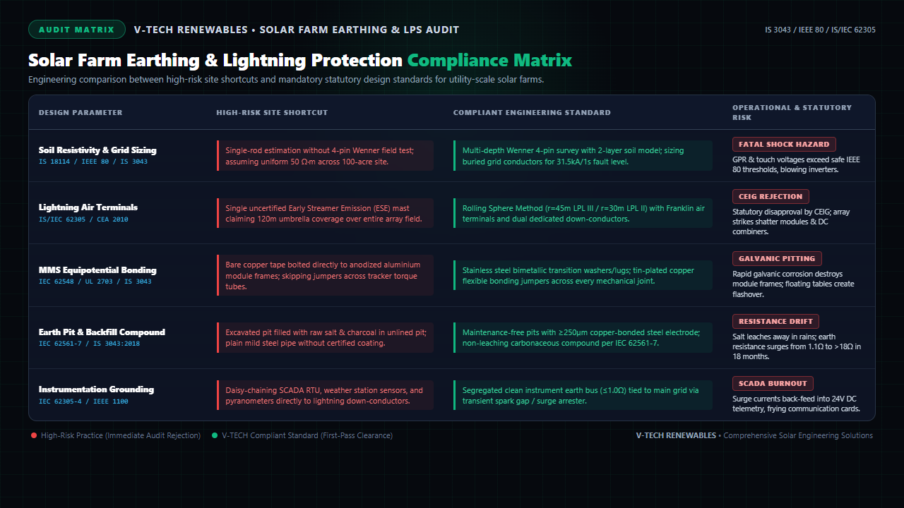
Figure 1: Comprehensive engineering audit matrix detailing 5 core earthing and LPS design vectors, field failure modes, and compliant Indian/IEC standards.
3. Equipotential MMS Table Bonding & Galvanic Corrosion Prevention
In a typical 50 MWp plant, over 80,000 individual photovoltaic modules are mounted across miles of steel racking. Every single metallic component must maintain low-impedance electrical continuity to the earth grid to safely drain leakage currents and electrostatic build-up.
The Electrochemical Trap: Aluminium to Copper Coupling
Solar module frames are fabricated from anodized aluminium alloy (electrochemical potential approx. -1.66 V). Earthing tape and bonding leads are commonly copper (+0.34 V).
When an installer bolts a bare copper lug directly against an aluminium frame flange in an outdoor environment, moisture acts as an electrolyte. The immense galvanic potential difference (>1.5 V) drives intense galvanic corrosion: the aluminium frame oxidizes and pits away within 12 to 24 months, structural strength crumbles, and the electrical bond severs completely.
The Engineering Fix: Under UL 2703 and IEC 62548, construction drawings must strictly prohibit direct copper-to-aluminium contact. Contractors must install:
- Bimetallic SS 304 / SS 316 Star Washers: Stainless steel acts as a neutral galvanic buffer between copper and aluminium.
- WEEB Grounding Clips: Specialized stainless steel clips equipped with sharp teeth that pierce through non-conductive anodized surface oxide layers during torque tightening.
- Tin-Plated Heavy-Duty Lugs: Electro-tinning provides a compatible electrochemical interface that prevents galvanic oxidation in corrosive coastal or industrial environments.
Inter-Table Jumpers & Dual Equipment Grounding
Single-axis tracker (SAT) torque tubes pivot on polymer bearings or grease-packed journal sleeves, creating high-resistance electrical breaks. Electrical drawings must mandate flexible tinned-copper braided bonding jumpers (minimum 16 mm² to 25 mm²) bridging every mechanical articulation joint and structural thermal expansion gap, guaranteeing an end-to-end table resistance of ≤ 0.1 Ω.
Furthermore, under Indian safety regulations, all major power conversion equipment—including central inverter containers, string combiner boxes, MV power transformers, and HT vacuum circuit breaker (VCB) kiosks—must feature dual independent equipment earthing connected to diametrically opposed nodes of the buried earth mat.
4. Maintenance-Free Earth Pits, Advanced Backfill & CEIG Clearance
The long-term impedance of an earthing system depends upon the quality and stability of its earth electrodes. Historical methods using unlined pits filled with alternating layers of raw common salt and wood charcoal are completely obsolete in modern utility-scale solar installations.
Why Salt and Charcoal Backfill Fails
Common sodium chloride salt is highly water-soluble. Over two to three monsoon seasons, rainwater percolates through unlined pits, leaching salts deep into surrounding water tables. Within 18 to 24 months, soil surrounding the electrode reverts to high resistivity, causing earth pit resistance to surge from an initial 1.2 Ω to over 15 Ω–20 Ω, triggering immediate non-compliance notices during mandatory annual CEIG audits. Furthermore, chlorine ions aggressively attack mild steel electrodes, causing premature corrosion pitting and structural severance.
Advanced Chemical Earth Electrodes (IEC 62561-7 / IS 3043)
Modern solar engineering designs specify maintenance-free chemical earthing electrodes:
- Electrode Metallurgy: High-tensile low-carbon steel rods coated with a continuous molecular layer of 99.9% pure electrolytic copper (≥250 µm thickness) per IEC 62561-2, or heavy-duty Class-B GI pipes (minimum 80 µm zinc coating).
- Non-Leaching Enhancing Compound: Pits must be backfilled with carbonaceous or sodium-bentonite based earth enhancement material conforming to IEC 62561-7. These compounds swell to 300% volume upon hydration, set like conductive concrete, resist rain washout, and maintain an intrinsic resistivity of ≤ 0.12 Ω·m to 0.20 Ω·m permanently without requiring seasonal salt-water recharging.
- Inspection Test Chambers: Heavy-duty precast concrete or Polypropylene (PP) chambers rated for ≥5-tonne wheel loads, fitted with a removable bolted copper/brass test link. This allows testing technicians and CEIG inspectors to isolate individual electrodes from the grid during four-terminal fall-of-potential testing.
5. Pre-Submission Drawing Checklist for Instant CEIG Approval
To avoid costly query letters and grid synchronization delays from DISCOMs and electrical inspectorates, EPCs must ensure their engineering submittal package contains complete, self-contained documentation:
| Drawing / Document Deliverable | Key Technical Inclusions | Statutory Standard Ref. |
|---|---|---|
| Soil Resistivity & Fault Calculation Report | Wenner 4-pin test curves, two-layer soil stratification model, conductor sizing calculation ($I_{sc} = 31.5\text{kA}$, $t = 1\text{s}$, $K=80$). | IS 18114 / IEEE 80 / IS 3043 |
| Overall Earth Mat Layout Drawing | Full plant coordinate grid, buried conductor size (50×6mm HDG flat), trench depth (600mm–800mm), perimeter loop ties, and riser locations. | CEA Regulations 2010 / IS 3043 |
| Lightning Protection 3D Layout Drawing | Rolling Sphere 3D interception arcs ($r=45\text{m}$ LPL III), Franklin rod elevations, down-conductor routes, and separation clearance verification. | IS/IEC 62305 (Parts 1–4) |
| MMS & Inverter Bonding Detail Drawing | WEEB clip assembly, bimetallic SS washer details, tinned copper flexible jumpers across torque tubes, and dual equipment earthing details. | IEC 62548 / UL 2703 |
| Earth Pit & Test Chamber Detail Sheet | Chemical electrode specs (250µm Cu-bonded steel), IEC 62561-7 compound backfill, precast chamber cross-section, and removable test link details. | IEC 62561-2 & 7 / IS 3043:2018 |
Frequently Asked Questions
1. Why is the Wenner 4-pin soil resistivity survey mandatory before sizing solar farm earthing grids?
Single-rod ground resistance measurements fail to reveal soil stratification across expansive 50-acre to 500-acre solar plant sites. Under IS 18114 and IEEE 81, a Wenner 4-pin survey measures apparent resistivity at varying pin spacings (e.g., 1m to 25m), enabling mathematical modeling of two-layer soil profiles (topsoil resistivity vs deep bedrock resistivity). Sizing the buried earthing mesh and electrode depth using stratified soil data prevents dangerous ground potential rise (GPR), ensures touch and step voltages stay below IEEE 80 physiological thresholds during 31.5 kA grid faults, and prevents statutory rejection during CEIG electrical safety audits.
2. Why do Indian DISCOMs and CEIG inspectors reject Early Streamer Emission (ESE) lightning arresters for solar arrays?
Under Central Electricity Authority (CEA) Technical Standards 2010 and IS/IEC 62305, lightning protection systems must adhere to physics-based interception principles using Franklin air terminals, roof conductors, or catenary wires evaluated via the Rolling Sphere Method (RSM). ESE terminals claim fictitious 'early ionization' radii up to 100 meters to 120 meters that lack validation under international IEC standards. Because an unvalidated ESE device leaves peripheral photovoltaic strings vulnerable to direct lightning strikes and side-flashing, state utilities (MSEDCL, GUVNL, BESCOM, TANGEDCO) mandate conventional Franklin rods and dedicated rolling sphere interception layouts.
3. How does bimetallic transition hardware prevent galvanic corrosion between module frames and earthing conductors?
Direct contact between bare copper earthing strips (+0.34 V electrochemical potential) and anodized aluminium PV module frames (-1.66 V) establishes an aggressive galvanic couple. In humid or outdoor monsoon environments, the aluminium acts as a sacrificial anode, pitting rapidly, degrading frame structural integrity, and eventually severing electrical bonding. Under IEC 62548 and UL 2703, EPCs must install stainless steel (SS 304/316) serrated star washers (WEEB clips) or tin-plated copper transition lugs, mechanically isolating the dissimilar metals while biting through anodization layers to guarantee an electrical resistance of less than 0.1 ohm.
Eliminate Grid Rejection with Audit-Ready Earthing & LPS Drawings
V-TECH RENEWABLES engineers bankable IEEE 80 earthing meshes, IS/IEC 62305 rolling sphere lightning models, and CEIG-compliant single line diagrams across Maharashtra, Gujarat, Karnataka, and Pan-India.
Related Technical Engineering Guides
V-TECH RENEWABLES Engineering Consultancy
Founded in 2009 in Pune, Maharashtra, V-TECH RENEWABLES has engineered over 500+ MWp of commercial, industrial, and utility-scale solar PV installations. Our engineering team specializes in detailed electrical design, STAAD Pro structural modeling, IEEE 80 earthing systems, and fast-track statutory grid interconnection dossiers.