Cable Tray Routing and DC Sizing: Best Practices for Safety and Efficiency
During the forensic commissioning audit of a 3.5 MWp commercial rooftop solar installation in Sanand, Gujarat, thermal imaging revealed cable tray internal temperatures spiking above 78°C during midday peak generation. The string cables—bundled indiscriminately in multi-layer bunches inside unventilated pre-galvanized trays—were suffering from severe thermal runaway. Measured DC voltage drop between the farthest module string and the string inverter reached 3.4%, draining over ₹14.5 Lakhs in annual generation value and triggering repetitive inverter over-temperature curtailment.
In competitive solar EPC execution, DC Balance of System (BOS) components represent less than 6% to 8% of initial capital expenditure, yet they dictate more than 60% of long-term operational failure risks. Sizing solar conductors purely on catalogue ampacity tables or treating cable tray routing as an afterthought creates permanent energy bleed, fire hazards, and regulatory rejection during statutory inspections.
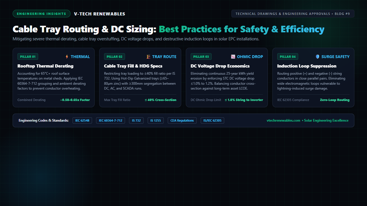
Achieving a durable, high-efficiency solar installation requires disciplined engineering alignment across four interconnected domains: rooftop microclimatic thermal derating, cable tray loading geometry, 25-year ohmic voltage drop economics, and electromagnetic surge suppression.
1. The Rooftop Thermal Reality: Why 45°C Ambient Means 70°C+ Cable Temperatures
Electrical cable catalogues commonly rate cross-linked polyethylene (XLPO) solar cables (such as EN 50618 H1Z2Z2-K) at an ambient baseline of 30°C or 40°C in free air. However, commercial metal roofs act as giant solar thermal collectors.
On an industrial shed in Maharashtra, Rajasthan, or Gujarat where daytime ambient air hits 42°C–45°C, solar irradiation absorbs into painted trapezoidal tin sheets. The microclimatic boundary layer within 50mm to 150mm of the roof surface regularly reaches 65°C to 72°C. When dozens of loaded DC string cables carrying 12A–16A continuous current are clustered in an enclosed tray, internal Joule heating ($I^2R$) traps heat, pushing jacket temperatures dangerously close to their 90°C maximum thermal endurance rating.
Under IEC 60364-7-712 and IS 732, design engineers must calculate true operational ampacity ($I_z$) using composite derating factors:
- ktemp (Thermal Correction): For 65°C ambient operating environments, XLPO derates by approximately 0.65x.
- kgroup (Bunching Factor): Bundling 6 to 9 circuits touching in a tray imposes an additional 0.68x to 0.72x derating factor.
- ktray (Installation Method): Enclosed or unventilated solid-bottom trays require a 0.90x penalty compared to open ladder racks.
When these factors compound ($0.65 \times 0.70 \times 0.90 \approx 0.41$), a 4mm² solar copper cable nominally rated for 55A in open air at 30°C derates to barely 22.5A. When modern bifacial high-power modules operate with short-circuit currents ($I_{sc}$) exceeding 15A to 18A, safety margins evaporate. Sizing standards dictate upsizing to 6mm² string conductors whenever runs exceed 35 meters or traverse high-heat roof zones.
2. Cable Tray Engineering: Perforated vs. Ladder, HDG Specs & Fill Limits
Cable tray physical layout dictates both thermal performance and physical survivability against mechanical deflection and coastal corrosion.
Perforated vs. Ladder Tray Selection
For industrial rooftops, perforated cable trays with ventilated covers provide the optimal balance: bottom perforations promote convective airflow while snap-on peak covers shield cables from direct UV breakdown, nesting birds, and rooftop maintenance foot traffic. Conversely, in large utility-scale ground-mount plants and central inverter yards, ladder-type cable trays with wide rung spacing (250mm–300mm) are essential to maximize air circulation around heavy aluminium DC main home-runs (1C × 240 / 300 / 400 mm²).
The 40% Fill Ratio Mandate (IS 732 / IEC 60364-5-52)
EPC contractors frequently attempt to save tray procurement costs by packing string cables three or four layers deep. Under IS 732 and national safety codes, cable tray cross-sectional fill must strictly remain ≤ 40%:
Maintaining single-layer cable lay with adequate spacing ensures every conductor dissapates heat into circulating air. During Chief Electrical Inspectorate to Government (CEIG) audits, overloaded trays trigger immediate compliance notices.
Physical Segregation and Metallurgy
Electromagnetic compatibility (EMC) demands physical segregation:
- DC String Cabling: Must run in dedicated trays isolated from AC power.
- AC Evacuation Feeders: Maintain a minimum 300mm air gap or continuous grounded metallic divider barrier between DC and AC trays to prevent high-voltage noise coupling.
- RS-485 / SCADA Instrumentation: Must be routed in separate shielded galvanized steel trays or conduits with ≥400mm clearance from power conductors.
For outdoor solar environments across India, trays fabricated from thin pre-galvanized sheet (10–15 µm zinc) fail within 24 to 36 months, rusting out at sheared edges. Structural drawings must specify Hot-Dip Galvanized (HDG) post-fabrication per IS 4759 and IS 2629, guaranteeing a minimum zinc coating thickness of 65 µm to 80 µm. Cables must be secured with SS 316 ladder ties or UV-stabilized Polyamide 12 ties at 1.2-meter intervals.
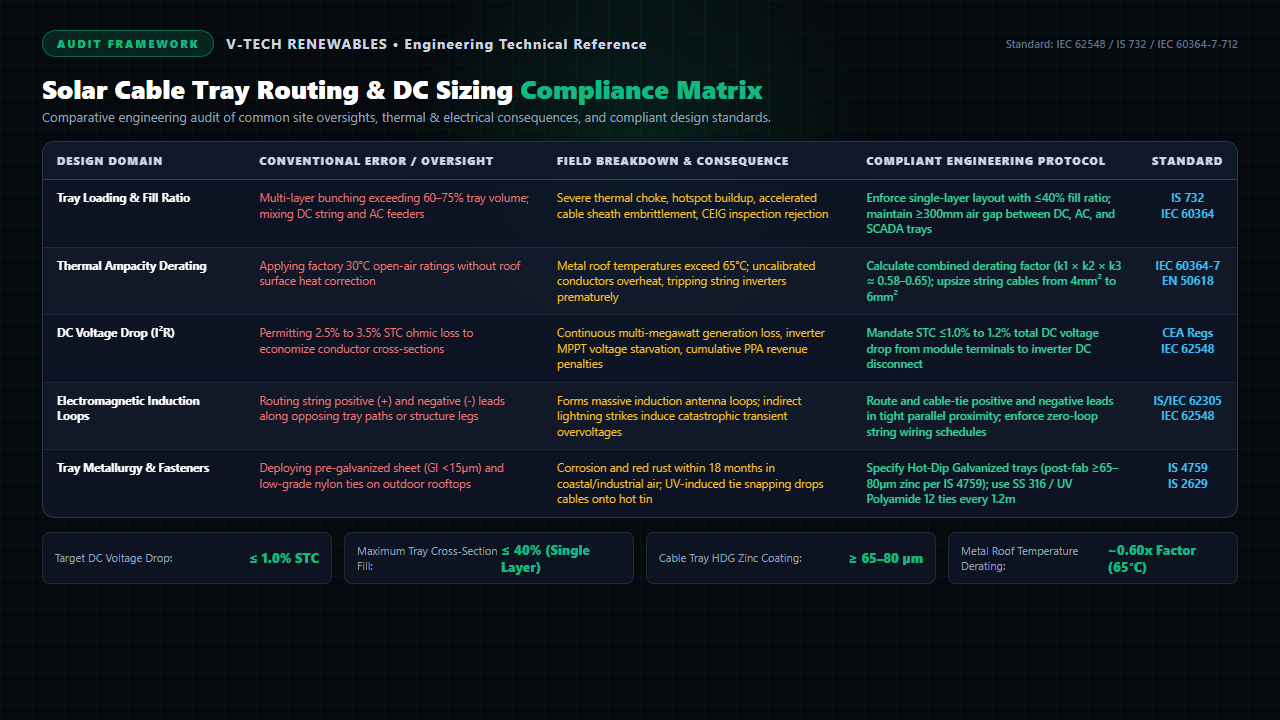
Figure 1: Engineering audit matrix detailing 5 core DC cable routing oversights, physical failure mechanisms, and compliant design standards.
3. DC Sizing & Voltage Drop Economics: The 1.0% STC Rule
Unlike AC utility grids where voltage drop primarily impacts equipment operating margins, DC voltage drop in photovoltaic systems represents permanent, non-recoverable kilowatt-hour energy generation loss every second the sun shines over 25 years.
Preliminary designs often compromise with a 2.5% to 3.0% voltage drop threshold to save capital cost on copper string conductors and aluminium home-run feeders. However, as demonstrated in our guide on correcting PVsyst simulation mistakes, ohmic loss increases linearly with temperature:
When conductors operate at 70°C in Indian field conditions, copper resistance increases by nearly 20% over factory STC (25°C) values. A cable designed for a 2.0% STC drop actually operates at 2.4%–2.6% field loss during high-irradiance periods when peak revenue is generated.
The Bankable Engineering Protocol: Enforce a strict maximum DC voltage drop of ≤ 1.0% to 1.2% at STC peak operating current (Imp) from the farthest PV module connector to the string inverter DC disconnect. In central inverter architectures, allocate ≤0.5% drop to DC string branch cables and ≤0.7% to main DC trunk cables. Over a 25-year lifecycle, investing an extra ₹2.5 Lakhs in upsized conductor cross-sections on a 1 MWp installation yields over ₹12 Lakhs in net incremental PPA revenue.
4. Suppressing Induction Loops to Safeguard Against Lightning Surges
One of the most dangerous and widely overlooked drafting errors in solar array layouts is the creation of electromagnetic induction loops.
When PV strings are wired across multi-table mounting structures, installation crews frequently route the positive (+) string lead along the top purlin and return the negative (-) lead along the bottom purlin or via an entirely separate cable tray on the opposite side of the array. This spatial separation forms a massive, open conductor perimeter—acting as a giant induction loop antenna.
Under IEC 62305-4 and IEC 62548, when a cloud-to-ground lightning strike discharges nearby, the high-frequency pulsed magnetic field ($\frac{dB}{dt}$) cuts across the loop area:
A loop area spanning just 20 m² can easily induce a transient surge exceeding 15 kV to 25 kV—far beyond the clamping capability of standard Type II DC Surge Protective Devices (SPDs). The resulting transient destroys module bypass diodes and vaporizes inverter MPPT input stages.
The Zero-Loop Wiring Protocol: Layout and shop drawings must mandate that the return conductor is routed directly adjacent to the string outgoing leads. Cables must be paired, strapped together, and routed along the same structural purlin or cable tray compartment, collapsing the effective loop area ($A_{loop}$) to near zero.
Solar DC Cable Routing & Sizing Compliance Matrix
To eliminate design failures and streamline statutory handovers, engineering teams must calibrate each installation parameter against established standards:
| Design Domain | Conventional Error / Oversight | Real-World Field Disconnect | Compliant Engineering Protocol | Reference Standard |
|---|---|---|---|---|
| Tray Loading & Fill | Multi-layer bunching exceeding 60%–75% tray volume; mixing DC string and AC feeders | Thermal choking, hotspot accumulation, accelerated insulation breakdown, CEIG audit rejection | Single-layer layout with ≤40% cross-section fill; maintain ≥300mm air gap between DC and AC trays | IS 732 / IEC 60364-5-52 |
| Thermal Derating | Applying factory 30°C ratings without rooftop solar boundary layer heat correction | Metal roof surface heat exceeds 65°C; undersized cables overheat, triggering inverter derating | Apply composite derating ($k_1 \times k_2 \times k_3 \approx 0.58–0.65$); upsize string cables to 6mm² | IEC 60364-7-712 / EN 50618 |
| DC Ohmic Loss (I²R) | Permitting 2.5% to 3.5% STC voltage drop to cut copper/aluminium procurement cost | Continuous 25-year kWh yield erosion, inverter MPPT starvation, cumulative PPA revenue penalties | Mandate STC ≤1.0% to 1.2% total DC voltage drop from module terminals to inverter DC disconnect | CEA Regs / IEC 62548 |
| Induction Loops | Routing positive (+) and negative (-) conductors via divergent structural rails or trays | Creates large induction antenna; lightning discharge induces 20kV+ surge, destroying inverters | Bundle and strap positive and negative leads in tight parallel proximity; enforce zero-loop schedule | IS/IEC 62305 / IEC 62548 |
| Tray Metallurgy | Deploying pre-galvanized sheet (GI <15µm) and commercial nylon cable ties outdoors | Corrosion and red rust within 24 months; UV embrittlement snaps ties, dropping cables on hot metal | Hot-Dip Galvanized post-fab ≥65–80µm zinc coating (IS 4759); SS 316 / UV Polyamide 12 ties | IS 4759 / IS 2629 |
Standardized Protocols for Zero-Defect Cable Execution
Solar developers and EPC contractors can ensure high-performance asset operation by enforcing three systematic quality control protocols:
First, integrate 3D cable tray polyline lengths directly into electrical CAD schedules before finalizing procurement bills of quantities (BOQ). As highlighted in our review of eliminating solar CAD drafting re-work, flat 2D drawings frequently miss vertical drops into trenches and inverter disconnect loops, leading to improper cable pulling and field splices prohibited by IEC 62548.
Second, require comprehensive cable schedule drawings that state conductor material, cross-sectional area, running length, operating current at STC, calculated STC voltage drop, and 70°C derated operating voltage drop for every individual string and main DC feeder. Align this documentation with our proven SLD best practices for C&I solar plants.
Third, partner with experienced engineering consultants during the detailed design phase. Explore our full suite of solar power plant design and engineering services to guarantee that your cable infrastructure delivers optimal generation, flawless CEIG compliance, and 25-year reliability.
Frequently Asked Questions
1. Why is ambient temperature derating critical for solar DC cables installed on metal rooftops?
While standard ambient air temperatures in industrial belts reach 42°C to 45°C during summer, the thermal boundary layer 50mm to 100mm above metal trapezoidal or zinc-alum roofing regularly exceeds 65°C to 72°C. Under IEC 60364-7-712 and EN 50618, continuous cable ampacity must be derated by approximately 0.58x to 0.65x. Failing to derate causes conductor core temperatures to breach 90°C, triggering thermal insulation degradation, increased ohmic resistance, and premature inverter DC clipping.
2. What is the maximum allowable cable tray fill ratio for solar DC string cables?
Under IS 732 and IEC 60364-5-52, the maximum permissible cable tray fill ratio is strictly capped at 40% of the tray's internal cross-sectional area, ideally arranged in a single layer with touching or spaced conductors. Overfilling cable trays restricts convective ventilation, traps heat within inner cable bundles, accelerates sheath embrittlement, and causes statutory rejection during CEIG electrical inspections.
3. How does minimizing induction loop area protect solar strings from lightning surges?
Under IEC 62305-4 and IEC 62548, routing the positive (+) and negative (-) conductors of a solar string along separate pathways or structure rails creates a large open loop antenna. When nearby cloud-to-ground lightning strikes occur, electromagnetic flux induces severe transient voltage spikes (tens of kilovolts) within the loop, blowing bypass diodes and destroying inverter MPPT input stages. Routing and strapping positive and negative leads in tight parallel proximity minimizes loop area to near zero, neutralizing induced surges.
About the Author
Written by the Engineering Team at V-TECH RENEWABLES, Pune—specializing in detailed solar electrical system engineering, cable schedule optimization, and IFC drawing packages across 500+ MWp of commercial, industrial, and utility-scale solar projects throughout India.