Navigating Setback Requirements in Rooftop Solar Engineering
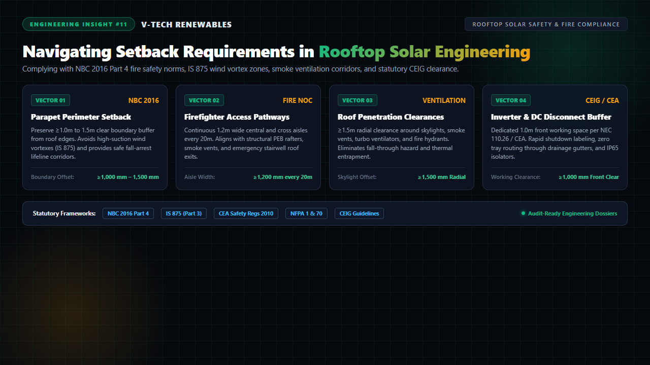
On an industrial pre-engineered building (PEB) in Chakan, Pune, a turnkey solar EPC contractor squeezed an additional 85 kWp of DC capacity by extending photovoltaic tables within 250 millimeters of the parapet gutters and covering several polycarbonate roof skylights. When the municipal industrial development authority and the Chief Electrical Inspectorate to Government (CEIG) conducted the mandatory joint pre-commissioning site audit, the inspection was summarily terminated.
The plant was slapped with a statutory stop-work notice: the design completely violated National Building Code (NBC 2016 Part 4) fire access corridors, failed to provide certified fall-arrest lifeline buffers, and placed module mounting clamps directly inside peak aerodynamic suction zones governed by IS 875 (Part 3:2015). The contractor had to demount 160 modules, re-route DC string Homerun cables, and submit re-engineered boundary layout drawings—costing over ₹12 Lakhs in lost yield and idle labor.
In commercial and industrial (C&I) rooftop solar engineering, boundary setbacks are not arbitrary aesthetic margins—they represent the vital intersection of life safety, structural survival under extreme cyclonic uplift, and swift statutory interconnection approval. Mastering boundary mapping requires balancing four critical engineering vectors: perimeter parapet offsets, internal firefighter access aisles, roof penetration clearances, and electrical working envelopes.
1. The Fire Safety Imperative & The Live DC Voltage Trap
Unlike conventional AC electrical distribution systems where tripping the main vacuum circuit breaker (VCB) de-energizes the entire facility, photovoltaic modules cannot simply be turned off. As long as ambient solar irradiance strikes the glass surface, PV strings generate open-circuit DC potentials ranging between 800V and 1,500V.
Statutory Fire NOC Requirements (NBC 2016 Part 4)
Under NBC 2016 Part 4 (Life Safety & Fire Protection) and state fire safety directives (such as MIDC, GIDC, PMRDA, and KIADB guidelines), municipal fire departments mandate clear, uninhibited roof access before issuing a Fire No-Objection Certificate (NOC). When an industrial fire breaks out, responding crews must perform vertical ventilation: cutting holes in roof decking or opening smoke dampers to release superheated gases and toxic smoke.
If solar modules cover the roof edge-to-edge, firefighters face mortal perils:
- Electrocution via Fire Streams: Spraying water or foam onto energized high-voltage DC arrays can conduct lethal currents back through fire hoses to nozzles.
- Compromised Roof Decking: Fire crews cannot identify weakened PEB purlins or sagging metal roof sheets concealed beneath dense module tables.
- Tripping & Arcing in Zero-Visibility Smoke: Technicians and emergency personnel traversing dark, smoke-filled roofs risk tripping over elevated cable trays or stepping onto glass surfaces, initiating catastrophic DC arc-fault flashovers.
2. Perimeter Parapet Setbacks & IS 875 Wind Suction Zones
Maximizing module density along roof boundaries is the most common blunder committed during initial sales engineering. Pushing tables flush against roof edges directly exposes module mounting structures (MMS) to severe aerodynamic turbulence.
Aerodynamic Suction Vortices per IS 875 (Part 3:2015)
When ambient wind strikes the vertical facade of an industrial building, the airflow separates sharply at the roof eaves, forming high-velocity conical suction vortices. Under IS 875 (Part 3:2015), rooftop surface zones are categorized into three discrete pressure regions:
Zone 2 (Eaves & Ridges): Cpe - Cpi reaches -1.2 to -1.5
Zone 1 (Interior Field): Cpe - Cpi drops to -0.6 to -0.8
The localized uplift force at the perimeter can be nearly triple the load experienced in the central field. Encroaching within 1.0m to 1.5m of the roof parapet places module clamps and lightweight cold-formed Z-purlins under extreme cyclical wind suction, frequently causing fastener pull-out, purlin warping, and frame detachment during heavy pre-monsoon squalls.
The Lifeline & Fall-Arrest Corridor
Under the Factories Act 1948 and IS 3521 (Industrial Safety Belts and Harnesses), operating technicians must maintain a secure lifeline system during routine module cleaning and drone thermography audits. Preserving a continuous 1.0-meter minimum (ideally 1.5-meter) clear perimeter setback allows safe installation of horizontal lifeline (HLL) steel anchor cables along parapet walls, ensuring O&M crews can work 100% tied-off without stepping beyond safety perimeters.
3. Firefighter Access Corridors, Smoke Ventilation & Skylights
Rooftop engineering layouts must break massive arrays into modular, compartmentalized blocks to allow rapid personnel transit and tactical fire venting.
Transversal & Longitudinal Access Aisles
In alignment with international safety benchmarks (NFPA 1 Fire Code Section 1205 / IFC Section 1205) and Indian CEIG guidelines, solar arrays must incorporate:
- Primary Fire Access Aisles: Minimum 1,200 mm (1.2 meters) clear width running continuously across both axes every 20 to 25 meters.
- Structural Alignment: Aisles must align directly over primary PEB structural steel frames (main portal rafters) rather than mid-span purlins, providing maximum load-bearing capacity for firefighters carrying heavy rescue equipment.
- Roof Egress Connectivity: Aisles must link directly to roof hatches, exterior caged cat-ladders, and emergency stairwell doors without requiring personnel to step over cable bridges or module racking.
Fragile Skylights & Turbo Ventilators
Industrial sheds extensively deploy translucent fiber-reinforced plastic (FRP) or polycarbonate skylights to achieve daylighting energy offsets. Covering or abutting these fragile surfaces with PV modules represents a double compliance failure:
- Deadly Fall Hazards: Fragile skylight sheets cannot support the weight of an installer. Accidental stepping leads to fatal roof falls. A strict 1,500 mm (1.5-meter) radial buffer must be demarcated on CAD layouts with physical toe-boards or painted hazard walkways.
- Thermal Vent Obstruction: Mechanical ridge exhaust fans and turbo ventilators expel internal factory heat. Placing solar modules within 1.5m–2.0m of industrial exhaust vents subjects modules to intense thermal air jets (>50°C–65°C), driving cell operating temperatures beyond 75°C, causing chronic voltage degradation, accelerated bypass diode aging, and severe hotspot formation.
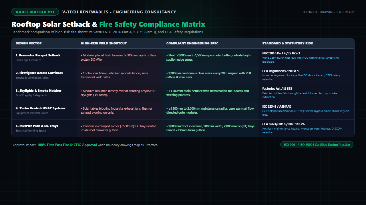
Figure 1: Comprehensive engineering compliance matrix detailing 5 core rooftop setback vectors, field failure modes, and statutory Indian/IEC benchmarks.
4. Inverter Working Envelopes, DC Rapid Shutdown & Cable Routing
String inverters and DC combiner switchgear mounted on rooftops require dedicated spatial envelopes to facilitate maintenance and guarantee operator safety during high-temperature operations.
Dedicated Working Enclosures (CEA 2010 / NEC 110.26)
Under Central Electricity Authority Safety Regulations and NEC 110.26, any wall or frame-mounted solar inverter requires an unobstructed working envelope:
- Front Working Depth: Minimum 1,000 mm clear in front of the inverter enclosure door when opened at 90 degrees.
- Lateral Working Width: Minimum 900 mm or the width of the equipment (whichever is greater), guaranteeing technicians clear escape routes in the event of an internal arc flash.
- Headroom: Minimum 2,000 mm vertical clearance beneath canopy sunshades to prevent operator head injuries.
Rapid Shutdown & Gutters Clearance
Construction drawings must demarcate the Rapid Shutdown Boundary (NEC 690.12 / CEA guidelines): DC voltages within 300mm of the array boundary must drop to ≤80V within 30 seconds of grid isolation. Furthermore, cable trays must maintain a minimum 1,000 mm setback from roof valley gutters and be elevated on 100mm pedestals to prevent immersion during monsoon cloudbursts.
5. Pre-Submission Boundary Mapping Checklist for Instant CEIG Approval
To avoid costly engineering revisions and statutory inspection objections, EPCs must ensure their physical layout package incorporates complete, unambiguous boundary callouts:
| Boundary Vector | Minimum Engineering Dimension | Mandatory Drawing Detail | Statutory Standard |
|---|---|---|---|
| Parapet Perimeter Setback | ≥1,000 mm – 1,500 mm continuous | Dimensioned outer perimeter line, lifeline anchor cable route, gutter clearance callout. | NBC 2016 Part 4 / IS 875-3 |
| Firefighter Access Aisles | ≥1,200 mm width every 20m | Continuous transversal walk paths aligned with main portal rafters and roof stairways. | CEA Regs 2010 / NFPA 1 |
| Fragile Skylight Safety Zones | ≥1,500 mm radial buffer | Hatched danger boundaries, protective toe-board installation detail, warning signage. | Factories Act / OSHA |
| Turbo Vents & HVAC Outlets | ≥1,500 mm – 2,000 mm radius | Thermal shadow circle, hot exhaust airflow diversion detail, zero module overhang. | IEC 62548 / ASHRAE |
| Inverter Electrical Working Pad | 1,000mm front × 900mm wide | Front clear working envelope, canopy clearance (≥2m), rapid shutdown label callout. | CEA 2010 / NEC 110.26 |
Frequently Asked Questions
1. Why do municipal fire authorities and DISCOMs mandate a minimum 1.0m to 1.5m perimeter setback on industrial roofs?
Under National Building Code (NBC 2016 Part 4) and Central Electricity Authority (CEA) Safety Regulations 2010, perimeter parapet setbacks provide an unobstructed 360-degree walkway for emergency responders and maintenance personnel. Photovoltaic strings remain energized at high DC potentials (up to 1,000V–1,500V) whenever exposed to sunlight, creating severe electric shock hazards for firefighters. Furthermore, IS 875 (Part 3:2015) wind pressure modeling demonstrates that intense aerodynamic suction vortices concentrate within 1.2m of roof eaves and ridges; maintaining perimeter setbacks keeps module clamps out of these peak turbulence zones to prevent purlin tear-out.
2. What are the statutory aisle dimensions for internal firefighter access corridors in rooftop solar layouts?
NBC 2016 Part 4 and international fire codes (NFPA 1 / IFC Section 1205) mandate continuous, straight transversal and longitudinal access pathways with a minimum clear width of 1,200 mm (1.2 meters) spaced every 20 to 25 meters across the module field. These pathways must align directly with structural building columns, emergency roof access stairways, fire hydrants, and smoke ventilation hatches, ensuring firefighters can advance charged attack hose lines and vent heat without stepping on glass module surfaces or tripping over elevated cable trays.
3. How should engineering drawings treat fragile roof skylights, smoke vents, and turbo ventilators?
Under the Factories Act 1948, OSHA standards, and CEA guidelines, layout drawings must designate a mandatory radial safety buffer of at least 1,500 mm (1.5 meters) around all fragile polycarbonate skylights and natural smoke release vents. Mounting PV tables over or directly abutting skylights creates a catastrophic fall-through hazard for maintenance technicians and blocks thermal buoyancy exhaust during internal factory fires. Drawings must call out permanent physical fall-protection toe-boards or high-visibility perimeter demarcation lines, alongside 1.5m–2.0m clearance around mechanical turbo ventilators to prevent hot-air exhaust impingement on adjacent PV modules.
Eliminate Inspection Rejection with Fire-Compliant Solar Drawings
V-TECH RENEWABLES engineers bankable, audit-ready rooftop solar layout drawings conforming to NBC 2016 Part 4, IS 875 Part 3, and CEIG safety mandates across Maharashtra, Gujarat, Karnataka, and Pan-India.
Related Technical Engineering Guides
V-TECH RENEWABLES Engineering Consultancy
Founded in 2009 in Pune, Maharashtra, V-TECH RENEWABLES has engineered over 500+ MWp of commercial, industrial, and utility-scale solar PV installations. Our engineering team specializes in detailed electrical design, STAAD Pro structural modeling, NBC 2016 fire safety layouts, and fast-track statutory grid interconnection dossiers.