Top 5 Reasons Utility Interconnection Applications Get Rejected
And how detailed electrical schematic drawings, protection coordination curves, and grid code compliance studies solve the approval deadlock for solar EPCs.
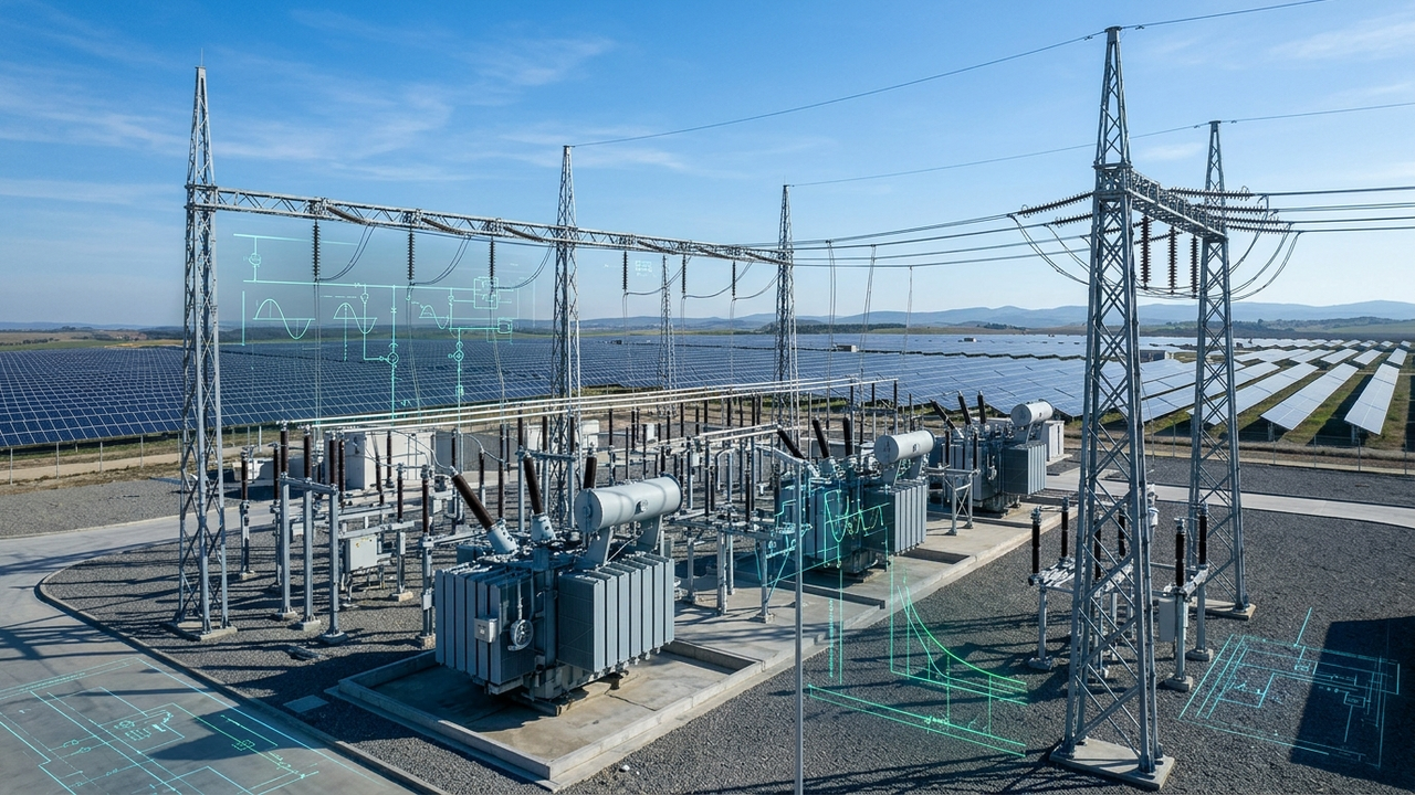
Securing grid interconnection approval from state distribution companies (DISCOMs), state transmission utilities (STUs), and the Chief Electrical Inspector to Government (CEIG) is the single most critical milestone in the lifecycle of any commercial, industrial (C&I), or utility-scale solar project. Yet, industry statistics across India reveal a harrowing reality: over 62% of initial solar grid connectivity applications face formal regulatory rejection, conditional holds, or exhaustive technical query loops.
For solar EPC contractors and asset owners, these administrative deadlocks are catastrophic. Every month of delayed grid synchronization bleeds debt service payments without generation revenue, threatens Power Purchase Agreements (PPAs) with punitive Liquidated Damages (often reaching ₹5,000 to ₹25,000 per MW per day), and freezes bank retention milestones.
Contrary to popular belief, utility rejections are rarely caused by political hurdles or transmission line congestion alone. In more than four out of five cases, rejections stem directly from inadequate, ambiguous, or mathematically uncoordinated electrical schematic drawings and technical engineering dossiers submitted by EPC drafting teams. When state grid engineers detect missing relay trip thresholds, unverified short-circuit fault ratings, or non-compliant Point of Common Coupling (PCC) demarcations, rejection is mandatory under grid safety statutes.
In this technical masterclass, the engineering team at V-TECH RENEWABLES deconstructs the Top 5 engineering failure modes behind utility interconnection rejections and details the exact schematic blueprints, protection coordination methodologies, and calculation frameworks required to achieve first-pass grid connectivity clearance.
1. Protection Coordination & Anti-Islanding Mismatch: The Zero-Tolerance Safety Trap
The primary responsibility of utility grid operators (such as MSEDCL, GETCO, BESCOM, or TSSPDCL) is preserving grid stability and safeguarding utility field maintenance crews against electrocution. When a grid fault occurs upstream, the solar plant must immediately disconnect from the affected feeder. If protection schemes fail, the solar inverter plant can establish an unintentional electrical island, maintaining energized conductors while line workers attempt repair operations.
Utility engineering review desks reject SLDs that treat the solar plant as a passive, non-directional load rather than an active distributed energy resource (DER). Under IEEE 1547-2018 (Clause 6.5) and the Central Electricity Authority (Technical Standards for Connectivity to the Grid) Regulations, the interconnection package must provide exhaustive protection coordination between plant-side circuit breakers and the grid substation feeder breaker.
⚡ 3 Mandatory Protection Coordination Deliverables Required on the SLD
- Dual Forward/Reverse Directional Overcurrent (ANSI 67 / 67N): SLD schematics must detail directional numerical relays on the 33kV/11kV incomer and evacuation bays. The relay must differentiate between utility-side upstream faults (tripping solar plant export within 100–150ms) and internal solar plant bus faults without tripping the grid feeder.
- Time-Current Characteristic (TCC) Discrimination Curves: The submission must include logarithmic TCC plots demonstrating a minimum grading margin of $\Delta t \ge 0.30\text{ seconds}$ between the solar evacuation breaker and the upstream utility substation relay across all fault current magnitudes.
- Certified Anti-Islanding Trip Windows (IEEE 1547 & IEC 62116): Schematics must detail over/under-voltage (ANSI 27/59: $V < 0.88\text{ pu}$ and $V > 1.10\text{ pu}$) and over/under-frequency (ANSI 81O/U: $f < 47.5\text{ Hz}$ and $f > 52.0\text{ Hz}$) trip thresholds, backed by Rate of Change of Frequency (ROCOF / $df/dt$) and Vector Shift (VS) passive trip algorithms clearing the feeder in under 2.0 seconds upon grid outage.
Submitting a generic single line diagram with blank relay circles (labeled merely "O/C & E/F Relay" without CT/PT ratios, relay models, ANSI device codes, or trip logic tables) triggers instantaneous application return. EPCs must supply stamped, manufacturer-validated Relay SLDs detailing primary and secondary CT ratios (e.g., 200-100/1-1A, 5P20 for protection and 0.2S for metering).
2. Prospective Short-Circuit Fault Exceedance: The Switchgear Explosion Risk
A catastrophic error committed during pre-bid engineering is sizing plant switchgear (vacuum circuit breakers / SF6 gas-insulated breakers) based solely on nominal continuous operating current rather than prospective utility busbar short-circuit fault MVA.
For example, a 10 MWp solar farm interconnecting at 33kV exports approximately $175\text{ A}$ nominal full-load current ($I_{fl} = P / (\sqrt{3} \times V)$). Procurement engineers frequently purchase standard 630A or 1250A indoor switchgear rated for 25 kA / 3-second short-circuit withstand capacity to minimize CapEx.
However, when the solar plant connects adjacent to a major 220kV/33kV or 132kV/33kV utility transmission substation, the prospective symmetrical grid fault current ($I_{sc}$) calculated per IEC 60909-0 often reaches 31.5 kA or 40.0 kA:
Under Central Electricity Authority (Measures Relating to Safety and Electric Supply) Regulation 35, installing circuit breakers or busbars whose rated short-circuit breaking capacity is lower than the calculated fault level at the Point of Interconnection is strictly illegal. Attempting to interrupt a 35 kA fault with a 25 kA breaker causes violent dielectric breakdown, arc-blast enclosure rupture, and immediate substation destruction.
When utility transmission engineers review the interconnection dossier, they examine the prospective fault study stamped by a Chartered Electrical Engineer. If the SLD fails to demonstrate adequate short-circuit breaking capacity ($I_{cu}$), dynamic peak making current capacity ($I_{cm} = 2.5 \times I_{cu}$ for 50 Hz systems), and busbar mechanical bracing against electromagnetic forces, the file is rejected immediately, forcing the developer into costly equipment replacement delays.
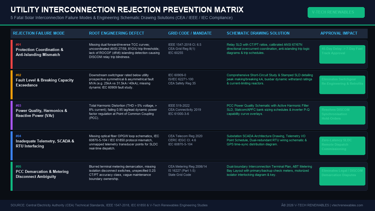
3. Power Quality Violations, Harmonic Distortion & Reactive Power (VAr) Deficits
With large-scale penetration of high-frequency power electronics (central and string solar inverters switching at 2 kHz to 16 kHz), utilities enforce strict power quality boundaries to prevent waveform distortion on nearby industrial and residential consumers.
Interconnection applications face rejection when EPCs cannot prove compliance with IEEE 519-2022 (Standard for Harmonic Control in Electric Power Systems) and the CEA Technical Standards for Connectivity to the Grid (Amendment 2019, Regulation B3):
- Harmonic Current & Voltage Distortion Limits: At the Point of Common Coupling (PCC), Total Harmonic Voltage Distortion ($THD_v$) must remain below 5.0%, with individual harmonic orders strictly limited (e.g., odd harmonics below the 11th order must remain below 3.0%). High-order pulse-width modulation (PWM) ripple must be attenuated by LCL inverter filters.
- Dynamic Reactive Power Capability ($\pm 0.95$ PF): CEA regulations mandate that every solar generating plant must deliver continuous dynamic reactive power support between 0.95 lagging (inductive) and 0.95 leading (capacitive) across the entire active power generation envelope (from 10% to 100% rated output).
- Night-time Reactive Power Support (Q at Night): In many states (such as Gujarat, Rajasthan, and Karnataka), transmission utilities demand that solar inverters or dedicated STATCOM / capacitor systems provide voltage regulation at the 33kV/132kV busbar even after sunset during peak non-solar load hours.
To overcome power quality objections, the engineering submission must incorporate an official PCC Power Quality Schematic. This includes inverter P-Q capability diagrams (showing kVAR output as a function of kW generation and ambient temperature), Active Harmonic Filter (AHF) sizing single lines, and automatic power factor correction (APFC) capacitor bank protection topologies with detuning reactors ($p = 7\%$ or $14\%$) to prevent dangerous parallel resonance with the grid.
4. Inadequate Telemetry, SCADA & Real-Time SLDC/RLDC Interfacing Architecture
In the era of modern grid management, unmonitored solar generation is considered a hostile grid disturbance. The Central Electricity Regulatory Commission (CERC) Indian Electricity Grid Code (IEGC) Clause 4.6 and the CEA (Technical Standards for Communication System in Power Sector) Regulations 2020 mandate real-time telemetry streaming from all renewable plants to the State Load Despatch Centre (SLDC) and Regional Load Despatch Centre (RLDC).
Despite completing physical plant construction, dozens of solar EPCs find their synchronization clearance held hostage for weeks because the telemetry documentation was treated as an afterthought. Common drafting errors that trigger instant rejection include:
📡 4 Fatal Telemetry & SCADA Documentation Omissions:
- Protocol Incompatibility: Submitting proprietary plant monitoring architectures (such as cloud IoT or basic Modbus RTU over RS-485) instead of standard utility-grade protocols—specifically IEC 60870-5-104 (telecontrol over TCP/IP) or IEC 61850 for substation automation.
- Missing Optical Fiber Terminal (OPGW) Schematics: State transmission utilities mandate dual redundant communication paths. The interconnection dossier must feature an OPGW Joint Box & Fibre Distribution Management System (FDMS) splice plan detailing optical link attenuation ($\le 0.22\text{ dB/km}$ at 1550 nm) from the solar switchyard to the utility substation terminal gantry.
- Unmapped Telemetry I/O Point Schedules: SLDCs require an exact signal schedule detailing analog values (MW export, MVAR exchange, 33kV bus voltages, grid frequency, ambient temperature, GHI irradiance) and digital telemetry status (circuit breaker open/close, isolator position, earth switch status, lockout relay 86 tripped, trip circuit supervision 95 healthy).
- Absence of GPS Time-Synchronization: Without a dedicated GPS / GLONASS master clock (providing 1 microsecond IRIG-B, PTP IEEE 1588, or SNTP synchronization) distributing timestamps to all numerical relays and Remote Terminal Units (RTUs), sequence-of-events (SOE) fault analysis is impossible, resulting in immediate SLDC clearance denial.
At V-TECH RENEWABLES, our engineers produce comprehensive Substation SCADA & Telemetry Architecture Drawings that illustrate the end-to-end communication hierarchy—from inverter data loggers and multi-function energy meters through redundant Ethernet switches, dual hot-standby RTU/FRTU panels, firewalls, and OPGW/PLCC links directly into the utility SCADA front-end processor.
5. Point of Common Coupling (PCC) Demarcation & Metering Demarcation Ambiguities
The Point of Common Coupling (PCC) is the legal, operational, and financial boundary where electrical energy transfers from the generator to the transmission or distribution utility. Vague, imprecise, or conflicting boundary lines on civil and electrical layout drawings represent one of the most stubborn causes of regulatory gridlock.
Disputes frequently erupt during CEIG site inspections because the submitted drawings fail to clarify:
- Visible Isolation Break Disconnectors: Utility operating protocols mandate that an external, gang-operated air break (GOAB) motorized isolator with a padlocked visible break and interlocked earth switch must be installed at the exact property boundary. If utility operators cannot physically confirm an open air-gap disconnection during line maintenance, grid synchronization will be denied on safety grounds.
- Dedicated ABT Tariff Metering CT/PT Units: Under the Central Electricity Authority (Installation and Operation of Meters) Regulations, metering must be executed via dedicated, independent CT/PT cores (typically Class 0.2S for energy metering) completely segregated from protection cores. Utilizing shared protection cores for tariff metering is strictly prohibited due to saturation inaccuracies during fault transients.
- Dual Main & Check Energy Meters: The schematic must feature two identical tri-vector four-quadrant ABT meters (Main Meter owned/maintained by the utility, and Check Meter owned by the developer) connected in series on secondary circuits, equipped with optical communication ports, automated meter reading (AMR) modems, and separate test terminal blocks (TTBs) enclosed in sealed, tamper-proof metering cubicles.
- Clear Maintenance & Custody Jurisdiction: The drawing must establish an explicit color-coded boundary dividing developer maintenance responsibility from utility ownership (including gantry towers, lightning arresters, drop-out fuses, and transmission terminal hardware).
Case Study: Fast-Tracking Grid Interconnection for a 25 MWp Solar Project in Maharashtra
To illustrate the tangible financial impact of meticulous schematic engineering, consider a recent 25 MWp utility solar project in Solapur, Maharashtra connecting to a 132/33kV MSETCL transmission substation:
Project Profile & Challenge:
The initial grid interconnection application submitted by the EPC was rejected by the state transmission utility citing three severe deficiencies: (1) inadequate 33kV switchgear breaking capacity (25 kA provided versus 31.5 kA prospective fault level), (2) non-compliant protection grading between the solar plant incomer and the 132kV bay breaker, and (3) missing IEC 60870-5-104 telemetry point tables for SLDC Kalwa. With commercial COD looming in 45 days, the developer faced ₹3.75 Crores in liquidated damages.
V-TECH RENEWABLES Engineering Intervention:
- Conducted rigorous dynamic short-circuit simulations in ETAP per IEC 60909, re-engineering the 33kV switchyard layout to integrate upgraded 31.5 kA / 3-sec VCBs with certified dynamic withstand calculations.
- Generated coordinated Time-Current Characteristic (TCC) relay curves establishing a 320ms grading margin with MSETCL's upstream distance and overcurrent protection relays (ANSI 21, 67/67N, 51/51N).
- Developed an end-to-end SCADA telemetry blueprint, including dual-redundant RTU wiring schematics, OPGW splice schedules, and an exhaustive 142-point IEC 60870-5-104 signal mapping table for SLDC integration.
- Compiled an authoritative CEIG compliance dossier with stamped clearance plans, earth mat touch-and-step potential calculations (IEEE 80), and lightning protection rolling sphere coverage diagrams (IEC 62305).
Quantified Commercial Results:
Pre-Submission Utility Interconnection Engineering Checklist for Solar EPCs
Prior to uploading your electrical dossier to state single-window clearance portals or submitting paper binders to the Chief Electrical Inspector, execute this 10-point technical audit:
| Check # | Audit Parameter | Governing Standard | Verification Requirement |
|---|---|---|---|
| 01 | Relay Coordination Curves | IEEE 1547 / IEC 60255 | Logarithmic TCC curves confirm $\ge 0.30\text{s}$ grading margin with utility substation feeder breaker across all fault magnitudes. |
| 02 | Directional Relays (ANSI 67/67N) | CEA Grid Connectivity Reg 8(1) | Directional overcurrent and earth fault protection deployed at 33kV incomer to prevent export trip blindness during grid disturbances. |
| 03 | Prospective Fault MVA Matching | IEC 60909 / CEA Safety Reg 35 | Switchgear symmetrical breaking capacity ($I_{cu}$) exceeds utility busbar fault MVA (e.g., 31.5 kA or 40 kA rated). |
| 04 | Anti-Islanding Trip Thresholds | IEEE 1547 / IEC 62116 | Voltage ($0.88 - 1.10\text{ pu}$), frequency ($47.5 - 52.0\text{ Hz}$), and ROCOF ($df/dt$) trip logic documented with $< 2.0\text{s}$ clearing time. |
| 05 | Power Quality & Harmonics | IEEE 519-2022 / CEA Connectivity | Total Harmonic Voltage Distortion ($THD_v < 5.0\%$) and individual harmonic limits verified at PCC; P-Q capability curve included. |
| 06 | Telemetry Protocol Conformance | IEC 60870-5-104 / IEC 61850 | RTU architecture details standard IP-based utility communication; complete analog and digital I/O signal schedule included. |
| 07 | OPGW Fiber & Redundancy Plan | CEA Telecom Reg 2020 | Fiber splice schedule, attenuation budget ($\le 0.22\text{ dB/km}$), and dual redundant communication routes illustrated. |
| 08 | Dedicated 0.2S Tariff Metering | CEA Metering Reg 2006/2014 | Class 0.2S dual-core CT/PT units dedicated solely to ABT Main & Check meters; separate sealable test terminal blocks (TTBs). |
| 09 | Visible Break Isolator Demarcation | State Grid Code / CEIG Norms | Motorized gang-operated air break (GOAB) isolator with interlocked earth switch detailed at developer/utility boundary. |
| 10 | Touch & Step Potential Safety | IEEE 80 / IS 3043 | Switchyard earthing grid calculation proves grid ground resistance $\le 1.0\ \Omega$ with safe mesh and step voltage thresholds. |
Frequently Asked Questions
Why do DISCOMs reject solar interconnection applications due to anti-islanding and protection coordination errors? ▼
Utilities reject interconnection packages when Single Line Diagrams (SLDs) fail to demonstrate dual-directional protection coordination between solar inverter plant trip curves and the grid substation feeder relays. Without calibrated directional overcurrent (ANSI 67/67N), voltage-dependent trip windows (ANSI 27/59), and passive/active anti-islanding relays (such as Rate of Change of Frequency / ROCOF df/dt per IEEE 1547-2018 and CEA Regulations), a grid fault can cause the solar plant to sustain an unintentional island. This poses extreme electrocution hazards for utility line-maintenance crews and damages downstream equipment upon out-of-phase auto-reclosing.
How does prospective short-circuit fault MVA exceedance cause switchgear approval failure under CEA Regulations? ▼
Solar developers frequently specify vacuum circuit breakers (VCBs) or SF6 switchgear based solely on nominal plant generation currents (e.g., 630A or 1250A) with standard 25 kA / 1-sec or 3-sec short-circuit withstand ratings. However, utility pooling substations at 33kV, 66kV, or 132kV often exhibit prospective network fault levels of 31.5 kA or 40 kA (per IEC 60909 calculations). Under Central Electricity Authority (Measures Relating to Safety and Electric Supply) Regulation 35, operating switchgear with symmetrical or asymmetrical breaking capacities below the grid busbar fault level is illegal due to violent explosion and arc-flash hazards. A certified dynamic fault level calculation and stamped relay SLD prevent this rejection.
What harmonic and reactive power (VAr) compliance studies are required by state utilities prior to synchronization? ▼
Per IEEE 519-2022 and the CEA Technical Standards for Connectivity to the Grid (Amendment 2019, Regulation B3), solar plants must maintain Total Harmonic Distortion (THD) within strict thresholds (voltage THD < 5% and individual harmonic order limits) and provide dynamic reactive power capability between 0.95 lagging and 0.95 leading power factor across all operating active power ranges. Rejections occur when applications lack a Point of Common Coupling (PCC) power quality schematic, inverter P-Q capability curve documentation, or sizing calculations for STATCOMs, Active Harmonic Filters (AHF), or thyristor-switched capacitor banks.
How do detailed SLD and SCADA telemetry architecture drawings resolve RTU communication rejections by SLDC/RLDC? ▼
State Load Despatch Centres (SLDC) mandate uninterrupted real-time telemetry data under the Indian Electricity Grid Code (IEGC) and CEA Technical Standards for Connectivity. Applications are rejected when schematics fail to show dual-redundant Remote Terminal Unit (RTU/FRTU) architectures, optical ground wire (OPGW) terminal splice trays, GPS time-synchronization distribution (SNTP/PTP per IEEE 1588), and comprehensive telemetry I/O mapping tables matching IEC 60870-5-104 or IEC 61850 protocols for active/reactive power, bus voltage, frequency, and circuit breaker status.
What constitutes a compliant Point of Common Coupling (PCC) metering demarcation plan for C&I and open access projects? ▼
A compliant PCC demarcation package requires a dedicated Interconnection Terminal Plan showing the exact physical and electrical boundary between the solar developer and the DISCOM/STU. It must specify 0.2S accuracy class dual-core CT/PT units dedicated to Availability Based Tariff (ABT) four-quadrant Main and Check tri-vector energy meters, separate test terminal blocks (TTBs) with sealable covers per CEA Metering Regulations, and an external Gang-Operated Air Break (GOAB) motorized disconnector with visible mechanical break and earth switch interlocks.
Authored by V-TECH RENEWABLES Engineering Division
Specialists in Solar Electrical Engineering, Substation Design, ETAP Grid Studies & CEIG Statutory Approvals.