Integrating Battery Energy Storage Systems (BESS) into Existing Solar Designs
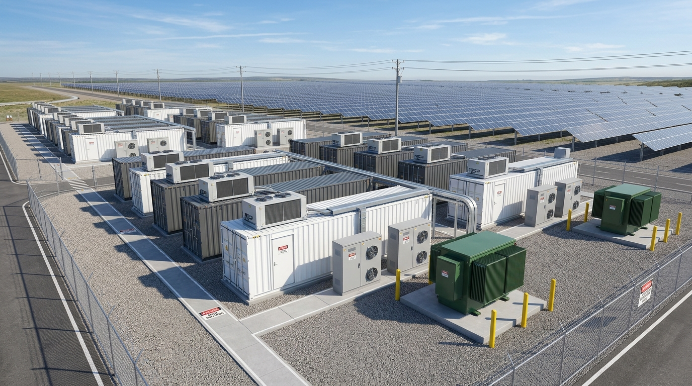
Across utility-scale solar farms and commercial & industrial (C&I) rooftop facilities, solar asset owners face an unprecedented operational dilemma: grid-mandated curtailment during peak midday insolation, stringent ramp-rate penalties imposed by State Load Despatch Centres (SLDCs), and escalating Demand Charges during non-solar evening peaks. The engineering antidote is retrofitting Battery Energy Storage Systems (BESS) to transform intermittent, sunlight-dependent PV assets into dispatchable, bankable Hybrid Solar-Plus-Storage Microgrids.
However, retrofitting multi-megawatt-hour containerized battery systems into an operating brownfield solar plant is far more complex than simply dropping shipping containers onto an empty gravel patch. It demands rigorous re-engineering across electrical interconnection topology, statutory fire separation setbacks (NFPA 855 / CEA Safety Regulations 2010), thermal runaway deflagration management (UL 9540A / NFPA 68), bidirectional numerical relay protection coordination, and heavy civil foundation plinth design (IS 456 / IS 2911).
A single oversight in busbar fault current calculations or thermal containment spacing can trigger catastrophic equipment fires, void OEM warranty covenants, or result in immediate statutory disconnection notices from the Chief Electrical Inspector to Government (CEIG). In this comprehensive engineering guide, V-Tech Renewables outlines the end-to-end technical blueprints for seamlessly and safely integrating BESS into existing solar PV infrastructure.
⚡ The Core Technical Imperative of BESS Integration
A standalone solar PV plant is an exclusively unidirectional generator, delivering power strictly according to incident solar irradiance. Adding a Battery Energy Storage System transforms the substation into a bidirectional four-quadrant power hub. The system must instantaneously absorb excess power during peak generation, discharge during grid contingencies or peak tariff windows, regulate frequency with millisecond response, and maintain strict thermal equilibrium without compromising plant short-circuit interrupting capacities.
1. Topology Selection: AC-Coupled vs. DC-Coupled Retrofit Architectures
When integrating storage into an established solar infrastructure, the foundational engineering decision centers on the electrical coupling interface: AC-Coupling versus DC-Coupling.
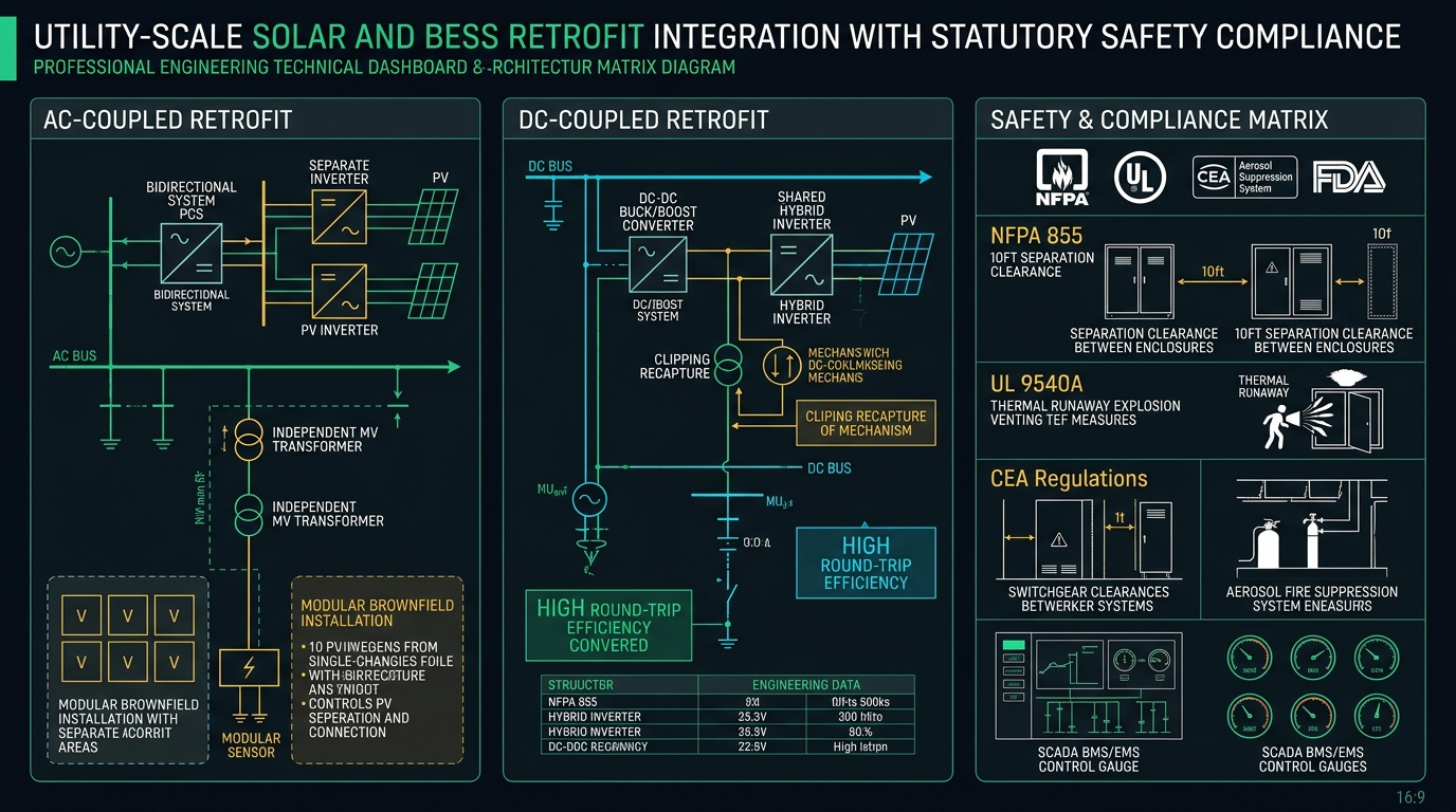
A. AC-Coupled Retrofit Architecture (The Industry Standard for Brownfield Assets)
In an AC-coupled system, the BESS operates as an independent power generation and consumption island. The battery container houses battery racks linked to dedicated bidirectional Power Conversion Systems (PCS)—four-quadrant inverters/rectifiers that interface with the plant via a dedicated medium-voltage step-up transformer (e.g., 0.69 kV / 33 kV):
- Zero Impact on Solar Inverters: Existing string or central solar PV inverters remain completely untouched. Their firmware, maximum power point tracking (MPPT) algorithms, and manufacturer warranties remain intact.
- Simplified Brownfield Commissioning: Storage capacity can be scaled independently of the solar array DC sizing. The PCS connects directly to a spare feeder breaker on the 33 kV substation indoor switchgear or taps into the plant MV pooling bus.
- Superior Redundancy: An outage or maintenance routine on the solar array does not interrupt BESS grid support services (such as frequency regulation or peak shaving), and vice versa.
- Efficiency Trade-off: Storing solar electricity requires two conversion stages (PV DC → AC through the solar inverter, then AC → Battery DC through the PCS bidirectional charger), yielding an overall Round-Trip Efficiency (RTE) of approximately 82% to 85%.
B. DC-Coupled Retrofit Architecture (Optimal for Clipping Recapture)
In a DC-coupled architecture, the battery storage connects directly to the 1,500V DC bus between the solar array combiner boxes and the existing central inverter stage using bidirectional DC-DC buck/boost converters:
- Solar Clipping Energy Recapture: In solar plants engineered with high DC-to-AC Overloading Ratios (e.g., DC/AC > 1.35 to 1.50), substantial generation is clipped during peak hours because the central inverter throttles input power. A DC-coupled BESS channels this clipped DC energy directly into battery charging without passing through the inverter bottleneck.
- Higher Efficiency: Energy flows directly from DC array strings through the DC-DC converter into the battery, bypassing double AC inversion and elevating RTE to 86% to 89%.
- Engineering Complexity in Retrofits: Requires breaking into operating 1,500V DC homerun cables, installing high-current DC blocking diodes, upgrading DC combiner boxes, and rewriting the central inverter's supervisory firmware to coordinate charging currents with MPPT tracking—often resulting in OEM warranty disputes on older solar assets.
2. Fire Safety & Spatial Separation: Deconstructing NFPA 855 & UL 9540A
Lithium-ion energy storage installations represent concentrated chemical and electrical energy densities. Consequently, statutory fire safety authorities and insurance underwriters enforce uncompromising spatial buffers around containerized BESS enclosures under NFPA 855 (Standard for the Installation of Stationary Energy Storage Systems) and CEA Safety Regulations 2010:
- The 10-Foot (3.05-Meter) Separation Rule: Outdoor containerized BESS enclosures must maintain a minimum clear horizontal separation of 10 feet (3.05 meters) from:
- Adjacent BESS container enclosures.
- Existing solar PV module structures and trackers.
- Medium-voltage pad-mounted step-up transformers and inverter skids.
- Plant site boundaries, control rooms, and public access roads.
- Fire Barrier Wall Exceptions: If site plot constraints preclude this 10-foot perimeter buffer, EPCs must construct 3-hour fire-rated blast barrier walls (conforming to UL 263 / IS 1646) extending at least 1.0 meter above and beyond the container footprint, preventing thermal radiation transfer between adjacent units.
- Emergency Firefighter Access Corridors: An unobstructed all-weather access road of at least 6.0 meters width with a turning radius suitable for heavy fire tenders must encircle the BESS enclosure zone, equipped with dedicated water hydrants delivering a minimum water flow of 1,900 L/min for at least 2 hours per NFPA 855 Chapter 4.
3. Thermal Runaway Mitigation & Deflagration Venting (UL 9540A & NFPA 68/69)
The paramount catastrophic risk in lithium-ion battery operations is Thermal Runaway—an exothermic chain reaction triggered by internal dendritic short circuits, mechanical puncture, overcharging, or ambient overheating. Once an individual cell reaches its critical thermal breakdown temperature, it releases flammable, toxic off-gases (including hydrogen, carbon monoxide, methane, and ethylene) at explosive concentrations exceeding the Lower Flammable Limit (LFL).
Multi-Tiered Explosion Prevention Architecture
Modern bankable BESS engineering integrates a layered defense mechanism adhering strictly to UL 9540A (Test Method for Evaluating Thermal Runaway Fire Propagation in Battery Energy Storage Systems):
4. Thermal Management & Chemistry: LFP Dominance and Liquid Cooling Thermodynamics
For stationary solar integration, Lithium Iron Phosphate (LiFePO4 - LFP) has completely supplanted Nickel Manganese Cobalt (NMC) chemistry across commercial and utility-scale installations. LFP offers inherently superior chemical stability:
- Thermal Runaway Threshold: LFP cells exhibit a thermal runaway onset temperature of approximately 270°C, compared to just 210°C for NMC chemistries, providing a vastly wider operating safety margin.
- Cycling Endurance: LFP delivers 6,000 to 8,000 cycles at 80% Depth of Discharge (DoD) under 0.5C/1C rates, translating into a bankable 15-to-20-year operating life matching typical solar plant lifespans.
- Non-Flammable Decomposition: Under extreme overtemperature failure, LFP releases significantly less oxygen than NMC, substantially lowering fire intensity and explosive overpressure hazards.
Liquid-Cooling Chillers vs. Legacy Air-Conditioning HVAC
In tropical and arid solar regions across India (such as Rajasthan, Gujarat, and Maharashtra where summer ambient temperatures frequently exceed 45°C), legacy forced-air HVAC systems fail to maintain thermal uniformity across dense battery racks:
Forced-Air Cooling HVAC (Legacy)
- Thermal Gradient: Cell temperature variance ($\Delta T$) across the container reaches 6°C to 8°C.
- Degradation Cascade: Warm cells age significantly faster than cold cells, forcing premature capacity throttling of entire series strings.
- Auxiliary Parasitic Load: High fan energy consumption consumes 6% to 9% of total stored energy.
Direct Liquid Cold-Plate Cooling (Modern Standard)
- Thermal Uniformity: Chilled water-glycol cold plates maintain cell temperature variance within $\Delta T \le 2.5^\circ\text{C}$.
- Extended Lifespan: Uniform thermal distribution extends battery operational lifespan by 15% to 20%.
- Energy Efficiency: Slashing auxiliary cooling parasitic consumption by 25% to 35%, boosting net plant round-trip yield.
5. Electrical Protection & Fault Current Coordination (IEEE 1547 & CEA Regulations 2010)
Integrating multi-megawatt four-quadrant bidirectional PCS inverters invalidates legacy substation short-circuit coordination studies. Under IEEE 242 (Buff Book), IEEE 1547, and CEA Technical Standards for Connectivity, the protection scheme must be comprehensively re-engineered:
- Bidirectional Short-Circuit Dynamics: In standard solar plants, fault current flows exclusively from the solar inverters toward an external grid fault. When BESS discharges into the network, it contributes high prospective fault currents (typically 1.1× to 1.3× rated current for inverter-based resources). Protection engineers must re-calculate symmetrical and asymmetrical fault levels per IEC 60909 to ensure existing 33 kV vacuum circuit breakers (VCBs) remain well within their breaking capacities (e.g., 25 kA / 31.5 kA for 3 seconds).
- Directional Overcurrent Coordination (ANSI 67 & 67N): Non-directional overcurrent relays (ANSI 50/51) on incoming feeders will experience nuisance tripping during BESS high-rate charging or discharging. Protection engineers must replace or reconfigure these relays with Directional Overcurrent and Earth Fault Relays (ANSI 67 / 67N), establishing independent forward (discharge) and reverse (charge) time-current characteristic (TCC) curves.
- Anti-Islanding & Grid Decoupling (ANSI 78 / 81R): If the utility grid trips, the combined solar-plus-BESS installation must not backfeed an unsynchronized islanded grid section, presenting fatal electrocution hazards to line maintenance crews. Protection panels must feature redundant anti-islanding schemes, combining passive Rate of Change of Frequency (ROCOF - ANSI 81R) and Vector Surge (ANSI 78) protection with active frequency-shift perturbation algorithms.
- High-Speed DC Semiconductor Protection: On the battery rack DC busbars, prospective short-circuit currents from massive low-impedance battery banks can exceed 50 kA within milliseconds. Standard thermal-magnetic breakers are too sluggish to prevent arc flashes. Racks must incorporate ultra-fast semiconductor fuses (Type aR) and specialized DC molded case circuit breakers (MCCBs rated for 1,500V DC) capable of clearing severe DC arcs within 5 to 10 milliseconds.
6. Civil Plinth & Heavy Structural Foundation Design (IS 456 & IS 2911)
A fully racked 40-foot modular BESS container housing 3.44 MWh to 5.0 MWh of lithium batteries, liquid chillers, and fire suppression systems weighs between 35 and 45 metric tonnes. This extreme dead load, concentrated on localized corner castings and center support pads, far exceeds standard solar inverter skid plinth parameters:
- Reinforced Concrete Raft Foundations: Foundations must be engineered as rigid Reinforced Cement Concrete (RCC) raft / mat foundations per IS 456:2000 using minimum M30 grade concrete with high corrosion-resistant Fe 500D or Fe 550D TMT reinforcement bars.
- Differential Settlement Thresholds: Heavy battery containers cannot tolerate torsional twisting. Foundations must be engineered for strict differential settlement limits (≤ 5mm across the container diagonal) to prevent racking frame distortion, cell pouch mechanical stress, and internal coolant pipe connection fractures.
- Flood Level Elevation: Under CEA Safety Regulations and insurance underwriting guidelines, the top of the concrete equipment plinth must sit at least 500mm above the calculated 100-year High Flood Level (HFL) of the local site.
- Secondary Containment for Coolant Spills: Civil drawings must include an integrated concrete containment trench around the plinth perimeter to collect accidental glycol-water coolant leaks, preventing environmental soil contamination.
7. Earthing & Lightning Protection Layouts (IS 3043 / IEEE 80 / IEC 62305)
Because containerized BESS assets combine volatile chemicals, high-voltage DC circuits (1,500V), and medium-voltage AC connections (33 kV), the grounding system must eliminate all prospective touch and step potentials under IS 3043:2018 and IEEE 80:2013:
Grounding & Interception Specifications
- Continuous Equipotential Earth Grid: A dedicated 50×6mm or 75×6mm hot-dip galvanized (HDG) steel tape or 95 sq.mm bare copper earthing grid buried at least 600mm deep, bonded directly to the plant's existing main earth mat.
- Skid & Enclosure Dual-Point Grounding: Every BESS container, PCS enclosure, and transformer skid must feature at least two distinct, diagonally opposite body earthing points connected to dedicated earth pits. Combined station earth resistance must not exceed $1.0\,\Omega$ under year-round conditions.
- Lightning Interception Shielding (IEC 62305): Battery containers act as large metallic structures in open terrain. Protection must be provided via dedicated Franklin air terminals or Early Streamer Emission (ESE) masts installed adjacent to (not directly on) the container roof, verified under rolling sphere analysis ($R = 20\text{m}$ for Class I protection) to prevent direct lightning attachment to deflagration vent hatches.
8. Case Study: 10 MWp Solar + 2.5 MW / 5 MWh BESS Industrial Microgrid Retrofit
To evaluate the financial and engineering viability of retrofitting BESS into an operating solar asset, examine this real-world retrofit implementation at an industrial manufacturing complex in Maharashtra:
📊 Operational & Financial Benchmarks: Pre- vs. Post-BESS Retrofit
- Midday Grid Curtailment: ~12% of peak generation lost
- Evening Peak Grid Tariffs: ₹11.50 / kWh (DISCOM TOD peak)
- Grid Outage Resilience: 0 hours (inverters immediately tripped)
- Diesel Generator (DG) Fuel Consumption: 42,000 L/month during outages
- Annual Carbon Offset: 11,800 MT CO₂
- Plant Equivalent Availability: 97.2%
- Midday Curtailment: 0% (100% captured into 5 MWh LFP storage)
- Evening Peak Shaving: Discharging 2.5 MW during 3-hour TOD peak
- Grid Outage Resilience: Instantaneous 2-hour microgrid islanding
- Diesel Generator Fuel Savings: 78% reduction in diesel burn
- Annual Carbon Offset: 14,250 MT CO₂
- Payback Period on BESS CapEx: 3.8 Years
9. Pre-Commissioning BESS Retrofit Audit Checklist for Solar EPCs
Prior to energizing containerized battery energy storage systems and synchronizing with the solar substation switchboard, EPC commissioning engineers and Owner's Engineers must audit this 8-point technical checklist:
- NFPA 855 Setback Verification: Confirm with laser distance meters that all 10-foot (3.05m) horizontal clear separations are maintained between BESS containers, transformers, solar arrays, and roadways.
- UL 9540A & NFPA 68 Deflagration Vent Clearance: Ensure roof-mounted deflagration vent panels have a minimum vertical clear discharge envelope of at least 3.0 meters free from overhead cabling, cable trays, or light poles.
- High-Speed Off-Gas Sensor Calibration: Verify that electrochemical Hydrogen ($H_2$) and Carbon Monoxide ($CO$) sensors are calibrated and successfully trigger automated HVAC purge fans and DC contactor trip coils during simulated test injections.
- Liquid Cooling Pressure & Leakage Tests: Conduct a 24-hour hydrostatic pressure hold test at 1.5× operating pressure on the closed-loop glycol-water chiller piping, confirming zero pressure drop across cold plates and manifold fittings.
- Directional Protection Relay Secondary Injection: Perform secondary current injection tests on ANSI 67/67N directional overcurrent relays, verifying trip times under simulated forward discharge and reverse charge fault currents.
- DC Insulation Resistance & Ground Fault Detection: Measure 1,500V DC bus insulation resistance to earth using a calibrated 2,500V DC megger (ensuring $R_{\text{ins}} \ge 50\,\text{M}\Omega$) and test automated trip response of the Residual Current Monitor (RCM).
- SCADA BMS-EMS Telemetry Integration: Verify sub-second communications between the Battery Management System (BMS), Power Conversion System (PCS), Energy Management System (EMS), and solar plant SCADA over IEC 61850 / Modbus TCP/IP protocols.
- Statutory CEIG & Fire NOC Documentation Dossier: Collate all OEM factory test certificates (FAT), single line diagrams stamped by a Chartered Electrical Engineer, soil resistivity logs, and local Fire Brigade NOC approvals for final statutory energization.
Frequently Asked Questions
Can a solar-plus-BESS installation restart an isolated grid during a total blackout (Black Start)?
Yes, provided the Power Conversion System (PCS) utilizes Grid-Forming (GFM) inverters equipped with Virtual Synchronous Generator (VSG) control algorithms rather than standard Grid-Following (GFL) technology. Grid-forming inverters can establish a stable voltage and frequency reference without an external utility grid signal, allowing the BESS to energize the local substation transformer, auxiliary loads, and progressively synchronize solar PV inverters in an islanded microgrid.
What is the expected auxiliary power consumption of a containerized BESS in summer?
Auxiliary parasitic consumption—comprising the liquid-cooling chiller pumps, internal dehumidifiers, BMS controllers, and safety systems—typically ranges between 2.5% and 4.0% of the battery's rated energy capacity per day for modern liquid-cooled systems. In contrast, older forced-air HVAC containers can consume up to 6.0% to 8.5% under extreme ambient temperatures (>42°C).
How do insurance underwriters assess fire risk in utility-scale BESS retrofits?
Leading global and domestic underwriters (such as Munich Re, Swiss Re, and Indian general insurers) require third-party validated UL 9540A unit-level and installation-level test reports. They mandate verification of automatic thermal off-gas detection, certified deflagration venting per NFPA 68, adherence to NFPA 855 physical separation buffers, and an on-site dedicated water reservoir capable of continuous cooling flow for at least 2 hours before issuing comprehensive property and business interruption insurance policies.
Does adding BESS affect the validity of existing solar module and inverter OEM warranties?
In an AC-coupled retrofit, existing solar module and inverter OEM warranties remain 100% protected because the storage system interfaces purely on the medium-voltage AC busbar downstream of existing equipment. In a DC-coupled retrofit, tapping into the 1,500V DC homerun cables can void inverter warranties unless the central inverter manufacturer provides formal engineering sign-off, updated firmware, and certified integration kits.
Seamlessly Integrate BESS into Your Solar Portfolio with V-Tech Renewables
Planning a battery storage retrofit, solar-plus-storage hybrid microgrid, or utility-scale capacity firming installation? V-Tech Renewables delivers turnkey electrical engineering blueprints, bidirectional protection coordination, NFPA 855 compliant layouts, and statutory CEIG approval dossiers.