3D Modeling vs. 2D Layouts: Which is Better for Large-Scale Solar EPC?
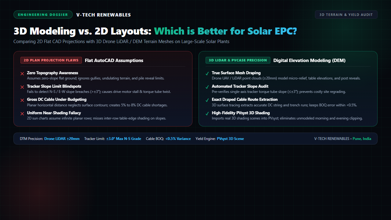
A 50 MWp solar plant in Rajasthan faced severe delays during mechanical erection: pile drivers hit unexpected gullies, single-axis tracker torque tubes jammed across uneven slopes, and DC string cables ran 6.8% short of procurement orders. The root cause? The engineering team relied on flat 2D AutoCAD layouts for rolling 3-to-6-degree terrain.
In utility-scale solar execution, drafting choices directly dictate balance-of-system (BOS) margins. While 2D drafting remains standard for basic feasibility, utility-scale developers and EPC leaders now face undulating land where planar geometry masks major structural and electrical risks.
Where 2D AutoCAD Layouts Fail on Real-World Terrain
A standard 2D layout projects the site onto a horizontal Cartesian plane. On flat terrain, this holds. On undulating acreage, flat drafting introduces three systemic errors during solar power plant design:
- Unseen Relief & Pile Reveal Spikes: Flat layouts ignore ground elevations. When posts encounter natural depressions, pile reveals exceed 0.8–1.0m design limits, requiring costly concrete encasements or heavier sections.
- DC Cable Shortages: 2D polylines calculate horizontal distance ($D_{plan}$), ignoring hypotenuse slope run ($D_{true} = D_{plan} / \cos\theta$) and vertical dropper drops into trench beds. This creates a 5% to 8% shortage in field DC cabling.
- Shading Blind Spots: 2D sun-angle charts assume uniform row elevations. Across sloped ground, adjacent tables cast unexpected morning and late-afternoon shadows that 2D models miss.
Tracker Slope Limits and 3D Digital Terrain Modeling (DTM)
Single-axis trackers (SAT) boost specific yield across high-irradiance zones like Gujarat, Karnataka, and Rajasthan. However, trackers operate within strict mechanical limits: torque tubes tolerate no more than ±3 degrees (approx. 5.2% grade) along north-south axes and minimal east-west table offsets.
3D Digital Terrain Modeling (DTM) integrates drone LiDAR point clouds (±20mm vertical accuracy) into engineering software. Algorithms test every tracker row against manufacturer slope specifications, flagging drive-motor binding hazards before civil contractors mobilize.
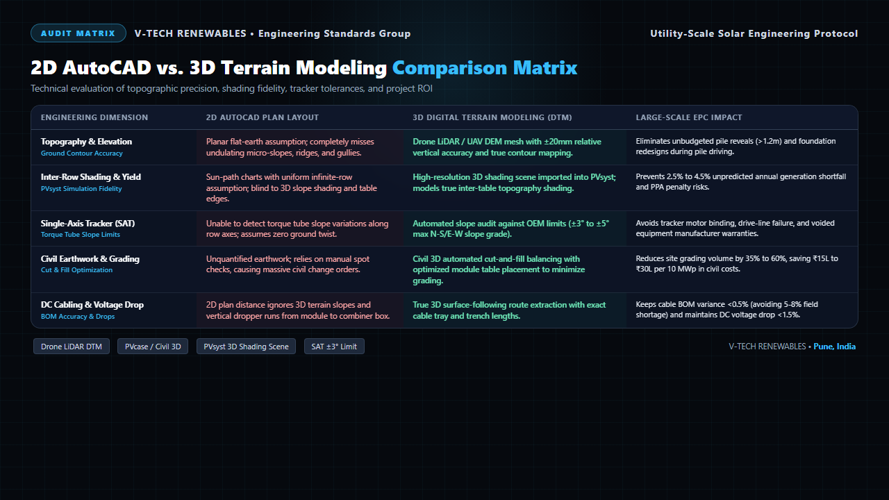
Figure 1: Technical audit matrix comparing 2D AutoCAD plan drafting against 3D Digital Terrain Modeling across utility-scale solar EPC parameters.
2D vs. 3D Solar Engineering Comparison Matrix
Evaluating layout options requires understanding how design accuracy impacts capital expenditure and operational yield:
| Engineering Dimension | 2D AutoCAD Plan Layout | 3D Digital Terrain Modeling (DTM) | Large-Scale EPC Impact |
|---|---|---|---|
| Topography & Elevation | Planar flat-earth assumption; misses micro-slopes, ridges, and gullies | Drone LiDAR DEM mesh with ±20mm relative vertical accuracy | Eliminates unbudgeted pile reveals (>1.2m) and foundation redesigns |
| Inter-Row Shading & Yield | Infinite uniform row charts; blind to 3D slope shading and table edges | 3D shading scene imported into PVsyst; models true inter-table slopes | Prevents 2.5% to 4.5% unpredicted annual generation shortfall |
| Single-Axis Tracker (SAT) | Unable to detect torque tube slope variations along row axes | Automated slope audit against OEM limits (±3° to ±5° max grade) | Avoids tracker motor stall, driveline failure, and voided warranties |
| Civil Earthwork & Grading | Unquantified earthwork; manual spot checks cause huge change orders | Civil 3D cut-and-fill balancing with table elevation optimization | Reduces site grading volume by 35%–60%, saving ₹15L–₹30L per 10 MWp |
| DC Cabling & Voltage Drop | Planar distance ignores terrain relief and vertical dropper runs | True 3D surface-following route extraction with exact tray lengths | Keeps cable BOQ variance <0.5% and maintains DC voltage drop <1.5% |
Field Protocols: When to Transition from 2D to 3D
Engineering directors should establish clear workflow thresholds for solar EPC execution.
First, 2D drafting remains cost-effective for small C&I rooftop plants under 200 kWp on flat RCC slabs or uniform industrial sheds where roof geometry is planar.
Second, 3D terrain modeling is mandatory for ground-mount projects exceeding 1 MWp, sites with slopes over 2 degrees, and all single-axis tracker projects. High-resolution drone mapping provides the elevation baseline, aligning with protocols in our guide on accurate site surveys.
Third, export validated 3D layouts directly into our PVsyst simulation workflow. Modeling terrain-draped near-shading scenes protects energy yield estimates and eliminates drafting errors detailed in our guide on solar CAD re-work. Coupled with STAAD.Pro structural verification per our guide on structural load calculations, 3D engineering secures bankable performance guarantees.
Frequently Asked Questions
1. Why do 2D AutoCAD layouts fail on undulating solar farm terrain?
2D CAD assumes a perfectly flat plane, measuring only horizontal distances. On sloped terrain (3°–8°), it neglects elevation contours, causing 5%–8% DC cable shortfalls, unbudgeted pile reveals exceeding 1.2m, and blind spots to inter-row slope shading.
2. How does 3D digital terrain modeling (DTM) protect single-axis tracker (SAT) warranties?
Single-axis trackers have strict north-south and east-west slope tolerances (typically ±3° to ±5°). 3D DTM with drone LiDAR analyzes terrain slopes along tracker torque tubes, preventing motor binding, structural twisting, and OEM warranty cancellations.
3. What is the yield difference between 2D pitch calculations and 3D PVsyst near-shading scenes?
2D calculations assume infinite, uniform rows on flat ground. Importing a high-resolution 3D terrain scene into PVsyst models mutual shading across sloped tables, early morning/evening terrain shadows, and edge effects, preventing 2.5% to 4.5% in unpredicted annual generation shortfalls.
About the Author
Written by the Engineering Team at V-TECH RENEWABLES, Pune—specializing in 3D digital terrain modeling, drone LiDAR topography analysis, and bankable PVsyst yield optimization across 500+ MWp of solar installations across India.