BOS Cost Reduction Through Optimized Structural Design
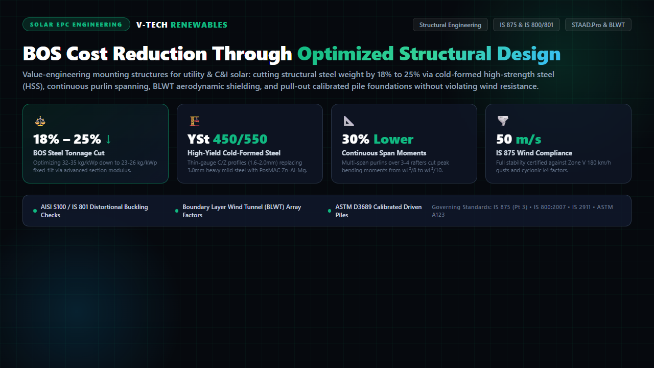
In utility-scale and commercial & industrial (C&I) solar photovoltaic projects, the Module Mounting Structure (MMS) and its civil foundation represent between 20% and 35% of total non-module Balance of System (BOS) CapEx. Across a 100 MWp utility solar asset, structural steel consumption typically oscillates between 3,200 and 3,600 metric tonnes. When steel commodity prices fluctuate, even a 3 kg/kWp structural variance can swing project procurement costs by ₹2.5 to ₹3.5 Crores—frequently evaporating the EPC contractor’s entire operating margin.
Faced with ultra-aggressive reverse-auction tariffs, many EPC purchase heads attempt to reduce structural expenditure by simply demanding lower steel weights from structure fabricators. However, indiscriminate down-gauging without rigorous finite element re-engineering creates fatal structural vulnerabilities: purlin web crippling, fastener tear-out during cyclonic gusts, harmonic torsional flutter on single-axis trackers, and catastrophic foundation pull-out failures.
True, bankable structural value engineering does not compromise structural integrity. By combining Cold-Formed High-Strength Steel (HSS YSt 450/550), continuous multi-span purlin kinematics, Boundary Layer Wind Tunnel (BLWT) aerodynamic array shielding, and geotechnical pull-out calibrations per IS 2911, forward-thinking solar engineers safely reduce BOS structural steel weight by 18% to 25% while fully satisfying Indian standard IS 875 (Part 3: 2015) and IS 800:2007 wind-load mandates.
1. The BOS Steel Dilemma: Capital Expenditure Squeeze vs. Structural Vulnerability
For over a decade, Indian solar engineering relied on conservative, industrial building-derived structural philosophies: heavy hot-rolled channels (IS 2062 Grade E250), simply supported single-bay purlin spans, generic tabular wind pressure coefficients, and deep concrete cast-in-situ bored piles. This resulted in cumbersome structures consuming 34 to 38 kg/kWp for fixed-tilt systems.
As solar modules escalated in physical dimensions—transitioning from legacy 72-cell 330W polycrystalline modules (2.0m × 1.0m, ~22 kg) to high-power 78-cell / 132-cell TOPCon and HJT modules exceeding 620W+ (2.4m × 1.13m, ~34 kg)—the wind sail area per table expanded by over 35%. Applying archaic structural design rules to these massive physical apertures forces EPCs into massive steel overdesign or, worse, arbitrary member down-gauging that causes catastrophic structural collapses during monsoon thunderstorms.
💡 The Mathematical Core of Structural Value Engineering
Structural capacity is governed by two fundamental criteria under Limit State Design (IS 800:2007): Strength (Ultimate Limit State, ULS) and Deflection (Serviceability Limit State, SLS). Steel weight is proportional to cross-sectional area ($A$), while bending strength depends on the section modulus ($Z = I / y$). Value engineering maximizes the $Z/A$ ratio (strength-to-weight efficiency) through geometric shape optimization and high yield strengths, ensuring that down-gauged profiles carry identical bending moments without violating $L/200$ deflection limits.
2. Wind Loading Dynamics: Deconstructing IS 875 (Part 3: 2015) & Gust Factors
The primary external force governing solar structure sizing is wind action. Solar tables act as inclined canopy aerofoils subject to intense positive downward pressures and violent negative suction uplift. Under IS 875 (Part 3: 2015), the design wind speed ($V_z$) at height $z$ is formulated as:
- $V_b$ (Basic Wind Speed): Varies from 33 m/s (Zone I, e.g., interior Maharashtra/Karnataka) up to 50 m/s (Zone V, coastal Gujarat, Andhra Pradesh, and Odisha).
- $k_1$ (Risk Coefficient / Probability Factor): Taken as 1.0 for 50-year design life or 0.90 for temporary agricultural installations. For bankable 25-year utility solar assets, standard practice enforces $k_1 = 0.92 \text{ to } 1.0$.
- $k_2$ (Terrain & Height Multiplier): Terrain Category 1 (exposed open terrain, sea coast) versus Terrain Category 2 (open plains with scattered shrubs, e.g., Thar desert). At ground level ($z \le 3\text{m}$), $k_2$ ranges between 0.93 and 1.0.
- $k_3$ (Topography Factor): Accounts for hill slopes, escarpments, and ridgelines. For ground slopes under 3°, $k_3 = 1.0$.
- $k_4$ (Importance Factor for Cyclonic Region): Enforces a critical 1.15 to 1.30 multiplier within 50 km of the eastern and western coastlines to safeguard against severe cyclonic storms.
The resulting design wind pressure $p_z = 0.6 \times V_z^2$ yields the base aerodynamic suction. A common mistake in pre-bid designs is assuming an average national wind pressure (e.g., $1.0\text{ kN/m}^2$) rather than computing micro-climate wind parameters. Overestimating wind pressure by 20% increases structural steel tonnage by up to 18%, whereas underestimating wind pressure in cyclonic zones triggers catastrophic roof purlin pull-out and frame folding.
3. Cold-Formed High-Strength Steel (HSS): Shifting from Mild Steel to YSt 450/550
The single most impactful lever in cutting mounting structure steel weight is migrating from conventional hot-rolled mild steel (IS 2062 Gr. E250, with a minimum yield strength of 250 MPa) to Cold-Formed High-Strength Light-Gauge Steel (conforming to IS 801 / AISI S100 / EN 1993-1-3):
- Yield Strength Surge: High-yield micro-alloyed structural steels, such as YSt 450 (yield strength $\ge 450\text{ MPa}$) and YSt 550 (yield strength $\ge 550\text{ MPa}$), deliver an 80% to 120% increase in load-bearing capability per unit of material compared to E250 steel.
- Gauge Reduction: Rafters and columns previously detailed in 2.5mm or 3.2mm hot-rolled profiles can be safely re-engineered into 1.6mm to 2.0mm cold-formed C-sections or Hat-sections without compromising structural load margins.
- Anti-Buckling Geometry: Cold-formed profiles are formed with specialized edge return lips ($c/t$ ratios) and longitudinal web stiffeners. These geometric enhancements arrest distortional buckling and local web crippling—the primary failure modes in thin-gauge structural steel members.
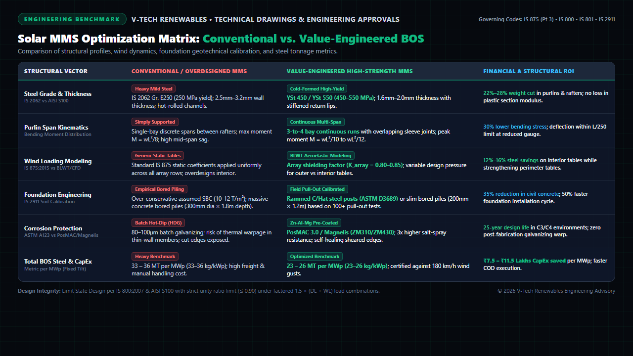
4. Continuous Multi-Span Purlin Kinematics: Slashing Peak Bending Moments by 30%
In standard solar array drawings, purlins are frequently detailed as discrete, simply supported beams spanning between two adjacent rafters (single-bay spans). Under uniform aerodynamic uplift or downward wind loading ($w$ in N/m), a simply supported beam experiences a maximum mid-span bending moment of:
In contrast, value-engineered mounting structures configure purlins as continuous members spanning across 3 or 4 rafter bays (utilizing nested overlapping sleeve splices or continuous roll-formed lengths up to 12 meters). In a continuous multi-span beam, the peak positive mid-span moment drops drastically, and negative bending moments develop over the interior supports:
This moment redistribution represents an immediate 20% to 33% reduction in peak design bending moment. Consequently, structural engineers can either:
- Reduce Purlin Thickness: Down-gauge the purlin from 2.0mm to 1.5mm while keeping the same rafter spacing, cutting purlin line steel tonnage by ~25%.
- Widen Rafter Spacing: Expand rafter pitch from 3.2 meters to 4.2 meters. Expanding rafter spacing reduces the total count of column uprights, purlin brackets, and ground pile foundations across the plant by up to 24%, yielding massive civil and mechanical labor savings.
5. Aerodynamic Shielding & BLWT Modeling: Beyond Generic Code Tabular Overdesign
Standard building codes like IS 875 (Part 3) and ASCE 7-16 were primarily written for standalone buildings, canopies, and billboards. When code tables are applied to solar PV arrays, they treat every solar table as an isolated canopy standing alone in an open field, prescribing extreme net pressure coefficients:
- Upwind Edge Pressure: $C_{pe} - C_{pi} \approx -1.8 \text{ to } -2.2$ (intense edge vortex suction).
- Interior Table Pressure (Code Assumption): Identical $-1.8$ suction enforced across every row in the solar field.
In reality, a utility-scale solar farm consists of dozens of repetitive parallel rows. When turbulent wind strikes the array, the first two perimeter rows act as an aerodynamic ramp, forcing the boundary layer upward and establishing a protective skimming flow. Boundary Layer Wind Tunnel (BLWT) testing and wind-tunnel calibrated aeroelastic codes prove that interior tables experience dramatic wind shielding:
The Array Shielding Factor ($K_{\text{array}}$)
Extensive aeroelastic studies across leading wind engineering institutes (e.g., CPP Wind, RWDI) establish that beyond Row 3, wind uplift pressures drop by 15% to 25%:
By zoning the solar farm into Perimeter Tables (High-Load Zone) and Interior Tables (Shielded Zone) in structural layout drawings, EPCs avoid over-engineering 85% of the plant's mounting structures. Interior tables utilize optimized lighter purlin gauges, while perimeter tables retain reinforced rafter sections and auxiliary diagonal bracings, saving thousands of steel tonnes across utility acreage.
6. Geotechnical Calibration: Replacing Over-Sized Concrete Piles with Driven Posts (IS 2911)
Civil foundations are the second anchor of structural BOS expenditure. A frequent source of capital waste is over-conservative empirical pile sizing. In the absence of early geotechnical fieldwork, EPCs often default to heavy bored cast-in-situ concrete piles (300mm diameter × 1,800mm embedment depth) based on generic desk estimates of Safe Bearing Capacity ($10 \text{ to } 12\text{ T/m}^2$).
Under IS 2911 (Parts 1 to 4) and ASTM D3689 (Standard Test Method for Deep Foundations Under Static Axial Tensile Load), foundation capacity is governed by:
- Vertical Tension (Uplift Pull-Out): Resisting the aerodynamic suction calculated under IS 875 through pile soil skin friction and pile self-weight.
- Lateral Resistance & Moment Capacity: Resisting horizontal wind shear without exceeding 5mm lateral deflection at the groundline.
- Compression Capacity: Carrying module, steel self-weight, and downward wind/snow load.
By executing 50 to 100 on-site pre-construction pull-out and lateral load tests across different soil strata, geotechnical engineers replace theoretical safety margins with empirical soil-pile adhesion values. In dense sands, clays, and gravelly strata, this enables a complete transition from costly concrete piles to directly rammed steel C-posts or Hat-posts:
- Zero Cement & Water: Eliminates concrete batching plants, transit mixers, water curing logistics, and 28-day curing delays in arid solar terrains.
- Rapid Deployment: Hydraulic GPS-guided pile-ramming rigs drive 250 to 350 posts per machine per day, compared to 40 bored concrete piles per auger crew.
- 35% Civil Cost Cut: Reduces foundation civil costs by ₹4 to ₹7 Lakhs per MWp while providing verified uplift capacities exceeding 25 to 35 kN per post.
7. Advanced Anti-Corrosion Metallurgy: PosMAC / Magnelis vs. Batch Hot-Dip Galvanizing
Value engineering thin-gauge structural steel demands rigorous long-term corrosion protection. Standard hot-rolled steel relies on batch Hot-Dip Galvanizing (HDG per IS 4759 / ASTM A123) with zinc coating thicknesses of 80 to 120 microns. However, when thin-gauge cold-formed members (1.5mm–2.0mm) are submerged into 450°C molten zinc baths, thermal stress induces severe member twisting, warping, and dimensional distortions.
Modern value-engineered solar mounting structures utilize advanced continuous pre-coated alloys: Zinc-Aluminum-Magnesium (Zn-Al-Mg) coated steel, marketed under proprietary brands such as PosMAC 3.0, Magnelis (ZM310 / ZM430), and Galvalume:
- Self-Healing Cut Edges: When Zn-Al-Mg steel is sheared, punched, or roll-formed on-site, magnesium ions migrate across the exposed raw steel edge to form a dense, insoluble simonkolleite protective film, neutralizing red rust formation.
- Superior Salt-Spray Longevity: Zn-Al-Mg coatings deliver 3 to 5 times higher corrosion resistance than standard pure zinc galvanizing in aggressive C3, C4, and coastal C5 environments per ISO 12944-2.
- Zero Thermal Distortion: Because coils are pre-coated under continuous factory conditions with precise coating mass tolerances (310 to 430 g/m²), cold-roll forming maintains razor-sharp tolerances (±0.5mm), eliminating on-site alignment delays during module bolting.
8. Case Study: 50 MWp Rajasthan Ground-Mount Solar Structural Value Engineering
To illustrate the financial and technical impact of optimized structural design, consider a 50 MWp utility-scale ground-mount solar project in Jodhpur District, Rajasthan:
📊 Pre-Engineering vs. Post-Optimization Benchmarks
- Steel Profile: IS 2062 Gr. E250 Mild Steel (2.5mm / 3.0mm)
- Purlin Layout: 2-bay simply supported single runs
- Wind Assumption: Uniform 47 m/s static code tables
- Foundation: 300mm dia × 1,600mm bored concrete piles
- Total Steel Consumption: 34.8 kg/kWp (1,740 MT)
- Foundation Cost: ₹68 Lakhs (concrete + augering)
- Steel Profile: Cold-Formed PosMAC YSt 450 (1.6mm / 2.0mm)
- Purlin Layout: 4-bay continuous nested sleeve runs
- Wind Modeling: BLWT zoned shielding ($K_{\text{array}} = 0.82$ interior)
- Foundation: Directly rammed steel C-posts (ASTM D3689 tested)
- Total Steel Consumption: 24.6 kg/kWp (1,230 MT)
- Foundation Cost: ₹41 Lakhs (driven pile mechanization)
9. Pre-Execution Structural Engineering & Peer Review Checklist for EPCs
Before finalizing procurement orders and issuing structural fabrication drawings for mass roll-forming, EPC technical heads and asset owners must verify this 7-point peer review checklist:
- STAAD.Pro 3D Space Frame Simulation: Confirm that the structural model incorporates full 3D spatial behavior, including non-linear P-Delta secondary effects, rafter-to-column semi-rigid joint releases, and diagonal brace pretension under wind reversals.
- AISI S100 / IS 801 Buckling Analysis: Cross-verify that thin-gauge sections have been evaluated for distortional, local, and flexural-torsional buckling. Ensure the effective section modulus ($Z_{\text{eff}}$) is utilized in stress calculations rather than gross section modulus ($Z_{\text{gross}}$).
- Combined Stress Unity Ratio Margin: Enforce a strict unity ratio threshold $\le 0.90$ under the governing load combination $1.5 \times (\text{DL} + \text{WL}_{\text{uplift}})$ to guarantee a 10% safety cushion against micro-burst wind anomalies.
- Fastener Pull-Out & Shear Calculations: Verify that purlin-to-rafter fastener connections (Grade 8.8 or Grade 10.9 hot-dip galvanized or stainless steel A2/A4 bolts) have been verified for bearing stress and sheet pull-through failure per AISI S100 Section J.
- Dissimilar Metal Isolation: On rooftop arrays with aluminum mounting rails or module frames resting on galvanized steel brackets, mandate UV-resistant EPDM or polyamide insulating washers to eliminate galvanic bi-metallic corrosion cells.
- Geotechnical Pull-Out Calibration Logs: Demand stamped pull-out test reports (ASTM D3689) conducted with calibrated hydraulic load cells across at least 1% of total plant pile locations before authorizing pile driving.
- Corrosion Coating Warranty Dossier: Confirm mill test certificates (MTC) proving minimum 310 g/m² Zn-Al-Mg coating mass (or 80μm HDG) with 25-year corrosion warranties adhering to ISO 9223 atmospheric corrosivity classifications.
Frequently Asked Questions
Can structural steel weight be safely reduced on single-axis tracker systems?
Yes, but with strict dynamic limitations. Single-axis trackers are susceptible to aeroelastic instability—specifically torsional flutter and galloping vortex shedding at stow angles. Rather than down-gauging torque tubes, structural optimization in trackers focuses on high-stiffness octagonal or circular torque tube profiles, dual-row synchronized slew drives, tuned mass dampers, and aerodynamic wind deflector skirts that suppress flutter frequencies while trimming purlin gauge.
How does module frame thickness affect mounting structure design?
Modern tier-1 module manufacturers have trimmed aluminum frame anodized heights from 40mm down to 30mm or 28mm to reduce shipping weights. Thinner module frames exhibit lower mechanical load ratings (e.g., 2,400 Pa wind / 5,400 Pa snow). Mounting structure purlin spacing and clamp landing widths must align precisely with the module's approved mounting holes or clamp zones; improper clamp positioning induces micro-cracks in solar silicon cells under high wind deflection.
What is the difference between PosMAC and standard Pre-Galvanized (GP) sheets?
Standard pre-galvanized (GP) coils have a pure zinc coating (typically 120 to 275 g/m²). When slit or roll-formed, the cut edges remain bare steel, rusting rapidly in humid or industrial atmospheres. PosMAC (POSCO Magnesium Aluminum Alloy Coating) contains 3% aluminum and 2.5% magnesium alongside zinc. The magnesium creates a self-healing film across cut edges, offering over 5 times the corrosion lifespan of standard GP sheets in aggressive rural, coastal, and black cotton soil environments.
Does reducing MMS steel weight void OEM structural warranties or bankability audits?
No, provided the value engineering is backed by third-party certified 3D STAAD.Pro / ANSYS simulations, certified pull-out test reports, and compliance certificates referencing IS 800, IS 801, and IS 875 (Part 3). Leading international lenders and Owner’s Engineers (such as DNV, TÜV Rheinland, and V-Tech Renewables) routinely approve optimized high-strength structures that prove structural unity ratios remain below 0.90 under ultimate limit state combinations.
Optimize Your Solar Mounting Structures with V-Tech Renewables
Planning a utility-scale solar farm or commercial rooftop portfolio? V-Tech Renewables provides end-to-end structural engineering peer reviews, STAAD.Pro finite element modeling, geotechnical foundation calibrations, and bankable structural optimization services that cut BOS CapEx without sacrificing safety.